
In this article, I will be taking a look at what Shader Graph is; using Shader Graph; the features of Shader Graph; how to create a simple shader with Shader Graph; some useful nodes with examples; and some things to look out for when looking at shaders created with older versions of Shader Graph. With this information, you should be ready to create some basic Shader Graph node effects!
I will leave you with some additional resources that you can check out — these can help you create and customize your own desired visual effects that couldn’t be covered in the scope of this article.
Here’s what you’ll learn:
The Replay is a weekly newsletter for dev and engineering leaders.
Delivered once a week, it's your curated guide to the most important conversations around frontend dev, emerging AI tools, and the state of modern software.
Before I get into Shader Graph, we need to know what shaders are and how they affect us.
Shaders are mini programs that run on the GPU that are used for texture mapping, lighting, or coloring objects. Everything that gets displayed on screen (a computer program or game, to include gaming consoles) goes through some sort of shader before it is displayed.
For most programs, this is built in automatically behind the scenes. In 3D modeling, software is usually added to the model before it is finally rendered. Film studios use them to render effects to the movie, and games use them to display everything.
If you use Unity, you are using them without even realizing it: everything displayed has some sort of material that uses a shader.
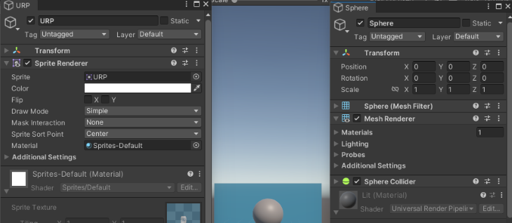
This image illustrates some of the different types of shaders available by default in Unity.
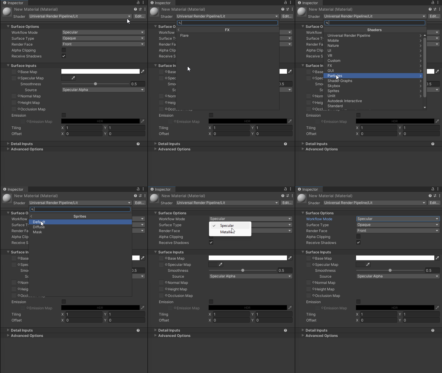
Now you may be asking yourself, If Unity already provides shaders that can be used, why do we care about shaders? The simple answer is that the default ones provided are bland and do not add anything special for use, like water, holographic, ghost, glow, or dissolve effects, just to name a few.
We can get some of these effects by changing the setting, like the Surface Type (Opaque or Transparent), specifying Metallic or Specular, Smoothness, or adding an Emission. The problem with this is they are all static. What we want are some dynamic effects or custom settings that we can use to add some polish to the look and feel of our game or application.
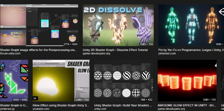
Let’s take a look at some of the different shader effects. These are just a small fraction of what is possible. Images are from an Internet image search for “Shader Graph Unity effects”:
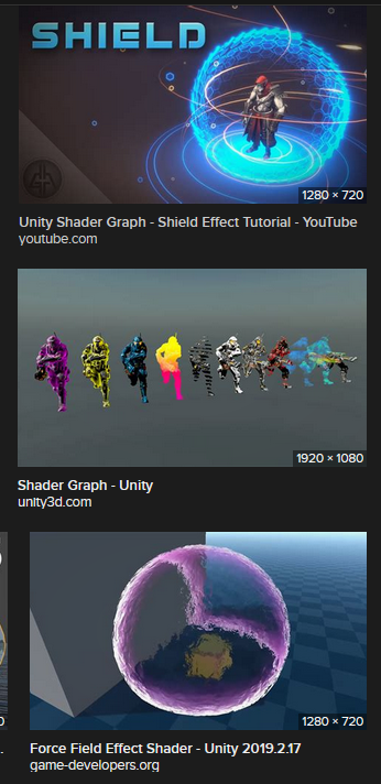
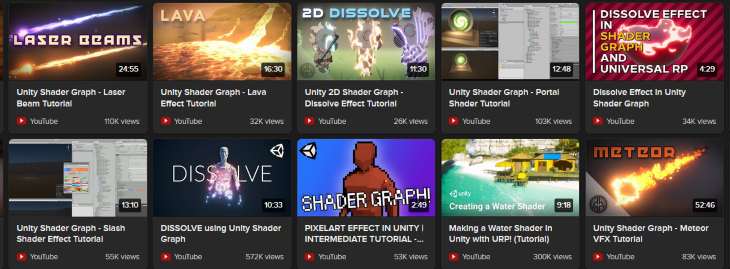
From a popular YouTube programming channel:

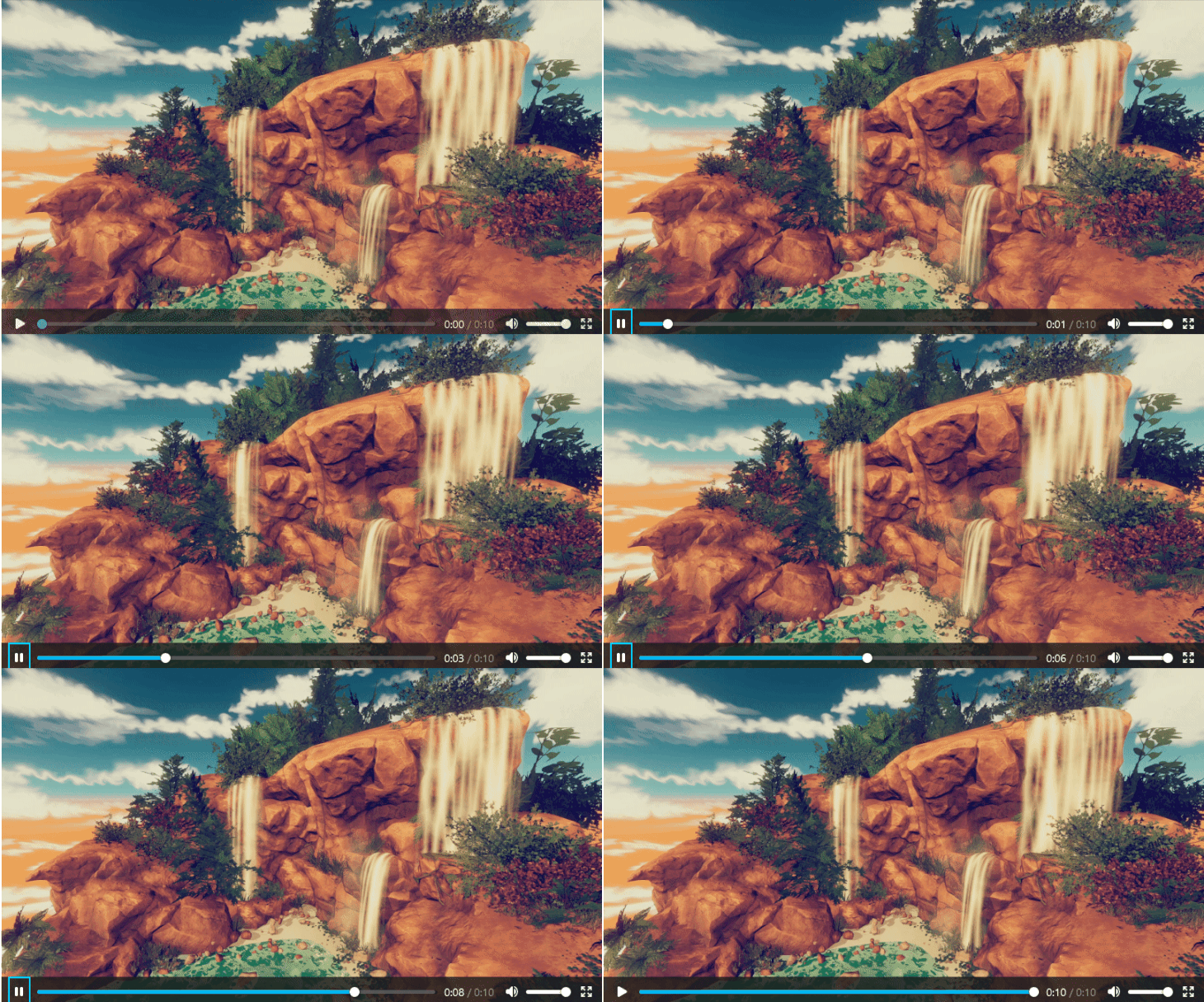
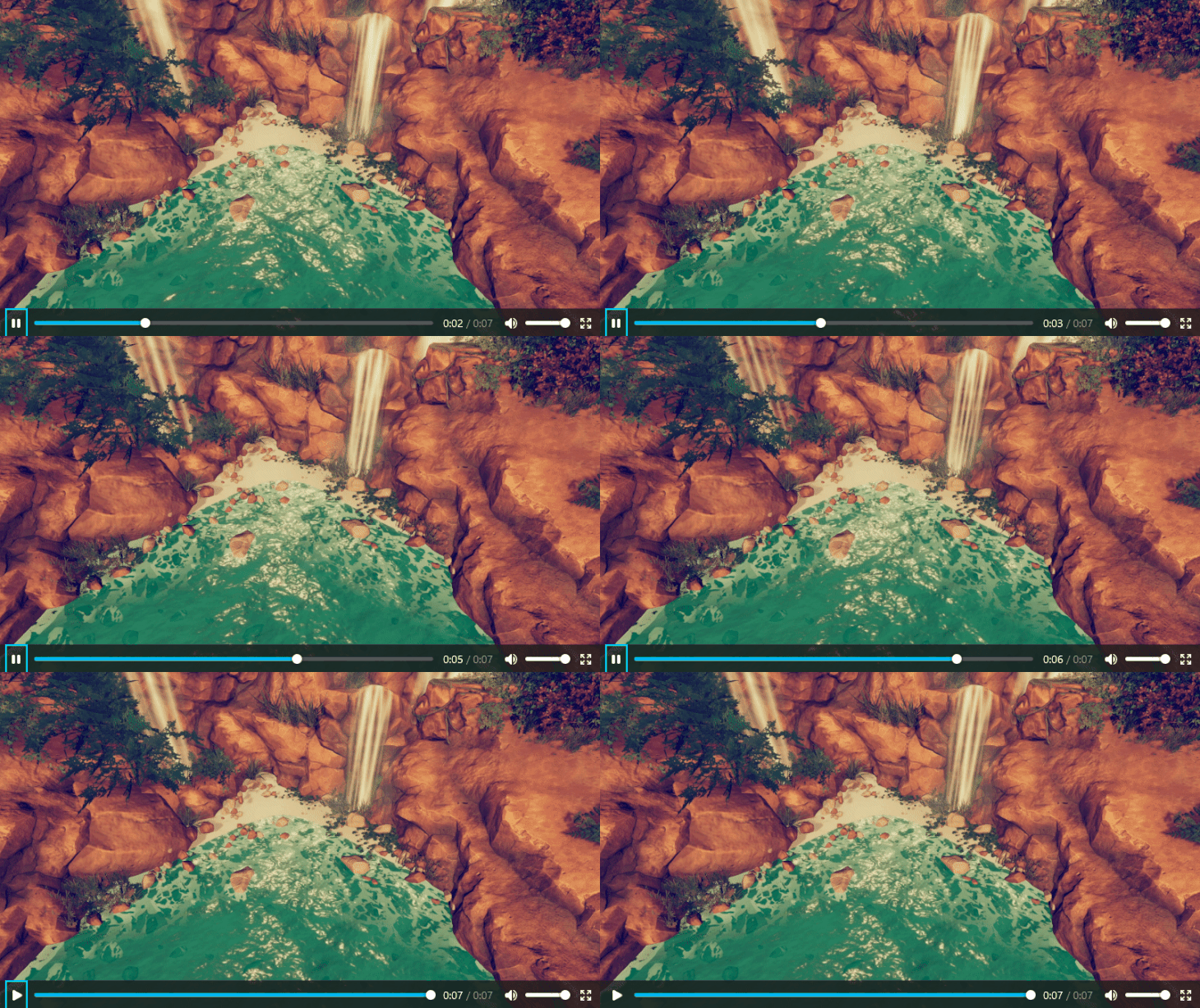
From the Unity blog:
Now that we know what shaders are and see some of the different possible effects that we can make from shaders, let’s take a look at how we can create those shaders.
Shaders used to be created through code; over the years, different software companies have been adding tools that allow the creation of shaders through visual node-based systems. Unity is no different; they have given us Shader Graph.
Refer to Unity’s Shader Graph features for the highlights: “Shader Graph enables you to build shaders visually. Instead of writing code, you create and connect nodes in a graph framework. Shader Graph gives instant feedback that reflects your changes, and it’s simple enough for users who are new to shader creation.”
Shader Graph was designed for artists, but programmers that are not shader programmers can also use it for easy shader creation. Hey, not all of us work with AAA studios that have the budget for a dedicated team of shader programmers/artists. Also, shaders can require a lot of knowledge of complex math and algorithms to hand-code.
For example, a snapshot of a new shader created in Unity does basic lighting of a model with a texture for the color. This is lines 1571 to 1580 of the 1685 lines of code:
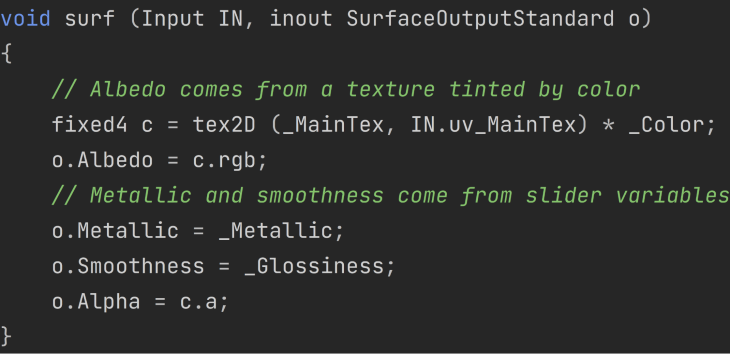
Unity notes these requirements to use Shader Graph:
Use Shader Graph with either of the Scriptable Render Pipelines (SRPs) available in Unity version 2018.1 and later:
As of Unity version 2021.2, you can also use Shader Graph with the Built-In Render Pipeline.
This means that as long as we are using one of the SRPs that we can use Shader Graph out of the box.
Even though we can install it with the Package Manager and use it with the Built-In Render Pipeline, Unity goes on to state, “It’s recommended to use Shader Graph with the Scriptable Render Pipelines.”
The first step is to create a new project in Unity Hub using the URP or HDRP template (or install one of the SRPs into an existing project).
Create a project using the URP or HDRP template.
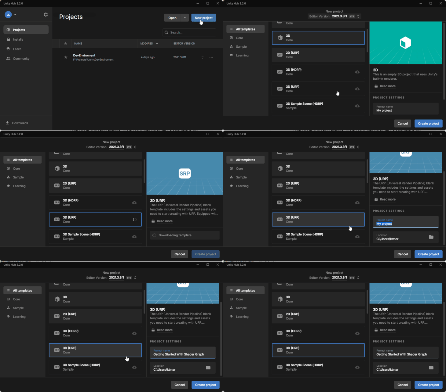
Once the scene loads, I add a capsule to my scene that I can use to display my effects with (feel free to use any 3D object that you want, to include your own model). I also create a material that I can apply my custom shader to and add it to my capsule.
Now that we have a very basic test scene, let’s create a new Shader Graph. Right click > Create > Shader Graph > SRP you want to use > type of shader.
In my case, I am going to use URP > Lit Shader Graph.
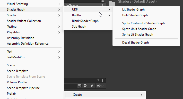
The Shader Graph menu will always contain Blank Shader Graph (a completely blank shader graph, no target is selected, and no blocks are added to the Master Stack) and Sub Graph (a blank Sub Graph asset, a reusable graph that can be used in other graphs) options.
There should be a submenu for each installed render pipeline that contains template stacks. In my case, I have URP and inbuilt submenus. The template creates a new Shader Graph that has the Master Stack with default Blocks and a Target selected. You can always change the settings in Shader Graph window later.
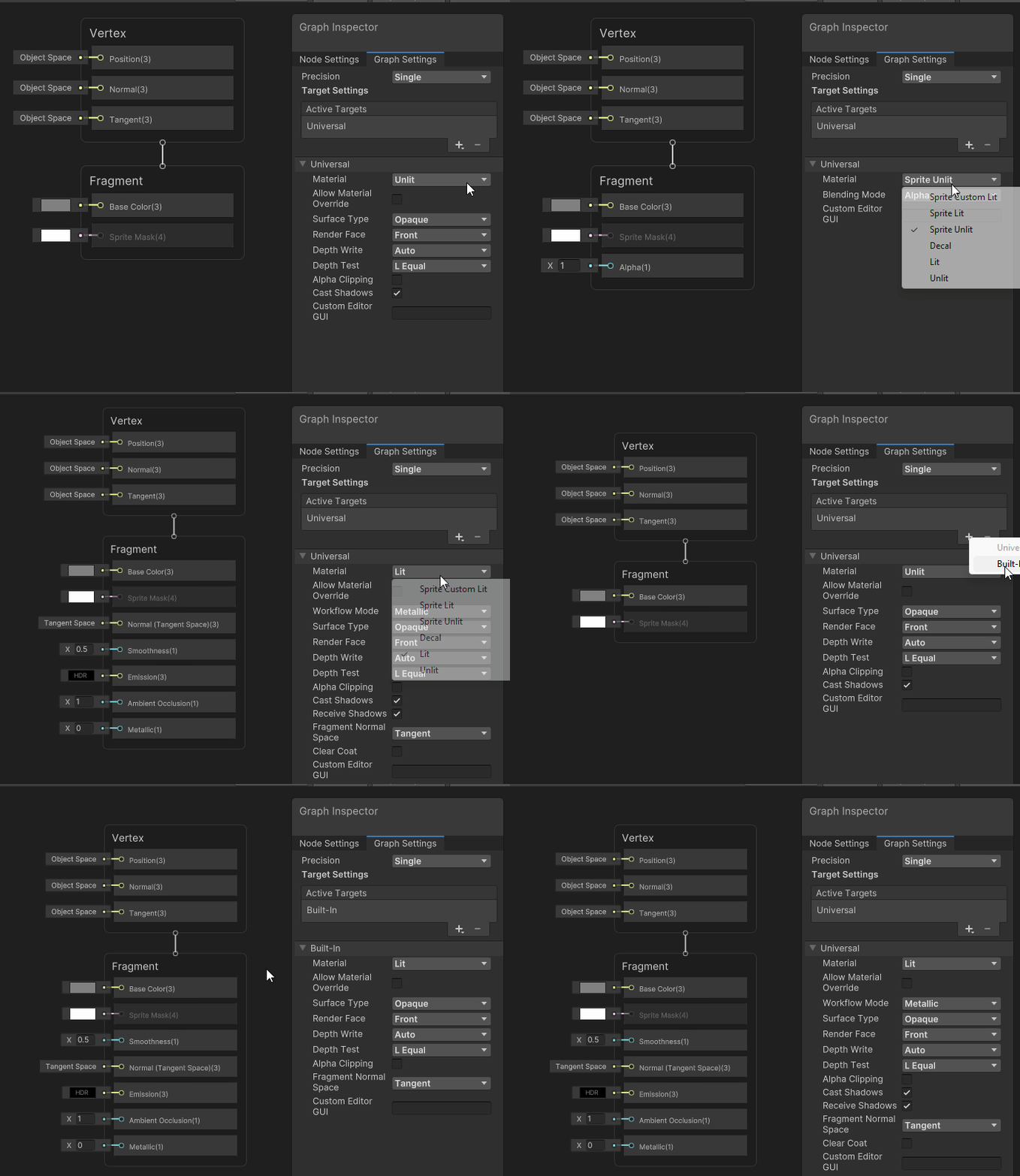
Now that we have a Shader Graph created, let’s set the material that we are using for this shader.
There are two ways to do this:
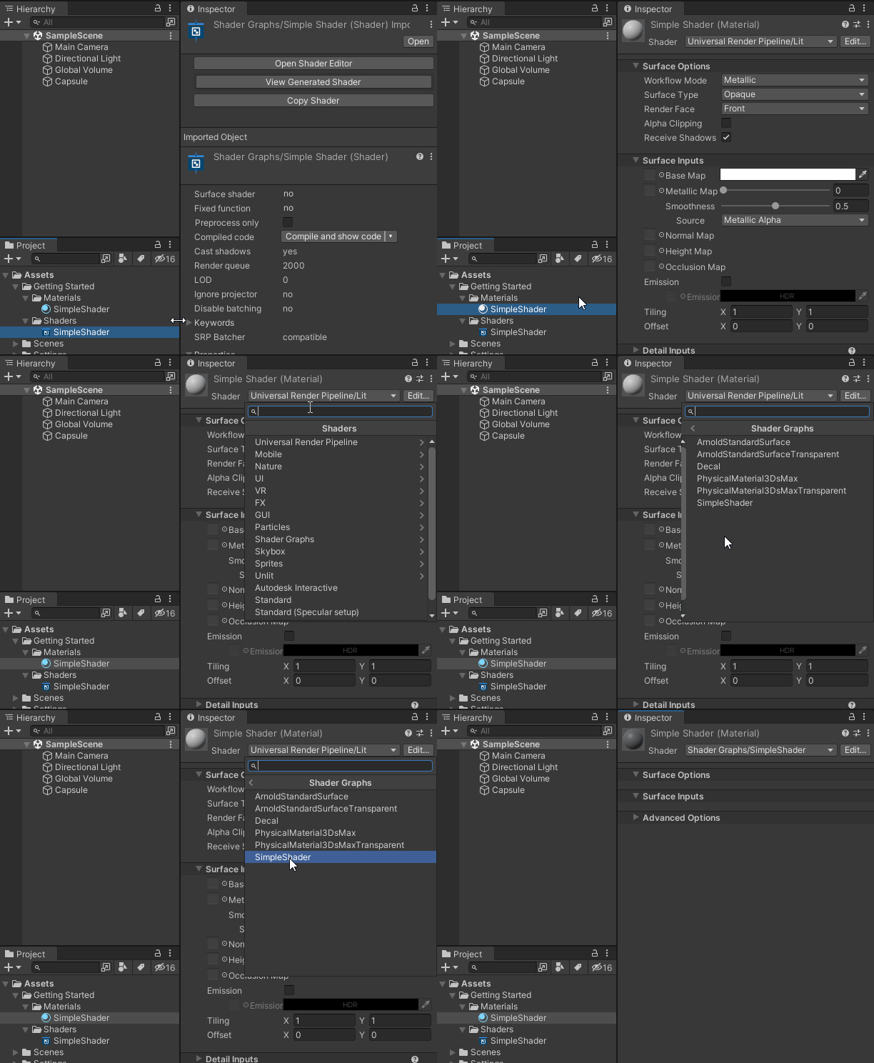
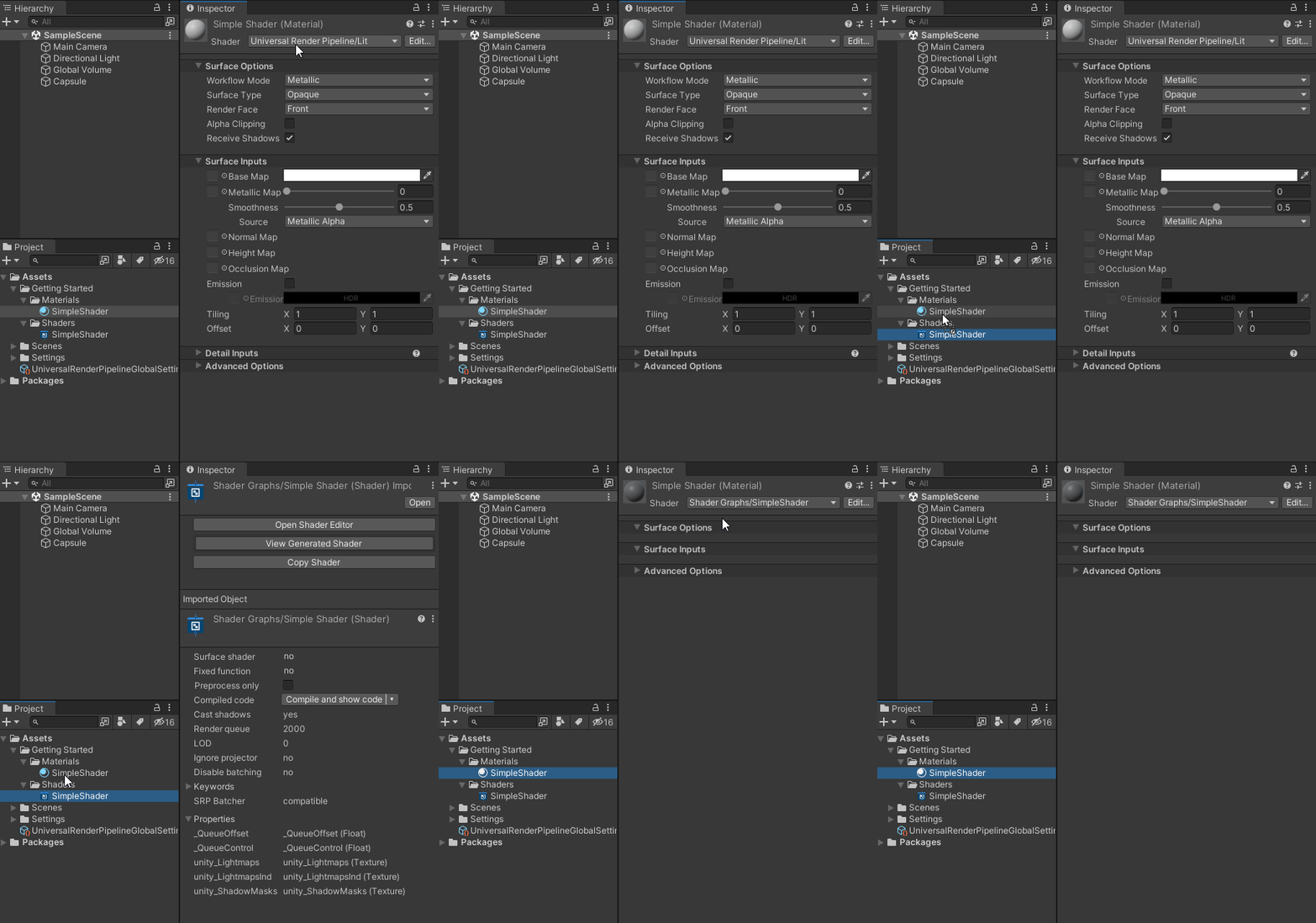
Now is a good time to pause and go over some useful terms, some of which I have already used; i.e., Master Stack, Blocks, Target.
Let’s also cover some more complicated terms in depth.
This is the render pipeline that the Shader Graph is for; you must have the render pipeline installed in your project for it to be available in the list. Not all blocks are compatible with all targets.
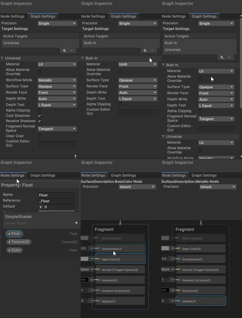
You can have multiple targets: this allows for easy creation of Shader Graphs that can be used in all render pipelines without having to do duplicate work. This can be changed in the Graph Settings.
These are variables that we can use to modify the shader’s values after it has complied.
For more info on properties, see the Unity docs.
All properties have the following settings. Other settings are available depending on the data type:
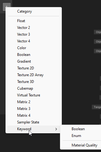
_. It’s automatically set to the Display Name; spaces are converted to _. You can change it. This name is used to access the property through C# script with the Material.Set and Material.Get methodstrue, the property will be exposed in the Material InspectorKeywords are used to create different variants for your Shader Graph (the shader behaves differently depending on the value of the keyword).
Keywords is an advanced feature and is beyond the scope of this article. As of writing this, Material Quality is the only type that has settings not able to change.
If you want to seek out more about keywords on your own time, the Unity docs are a good place to start.
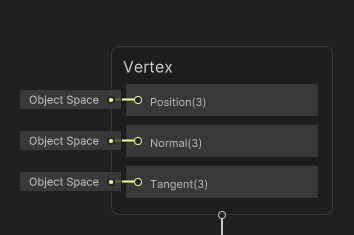
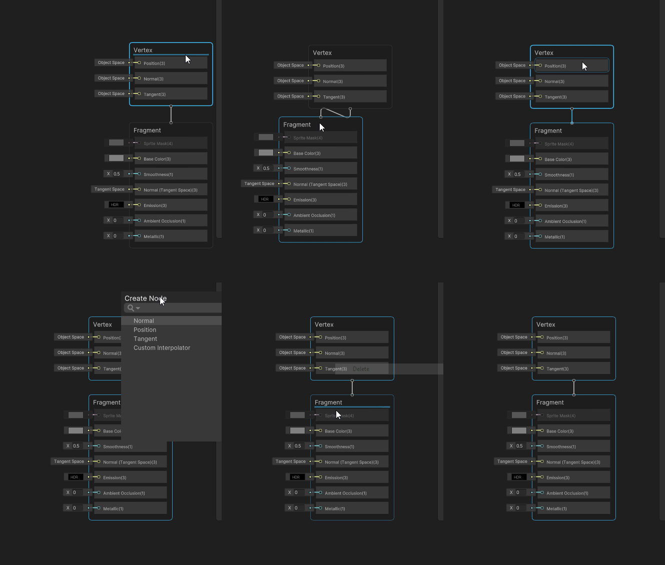
Block nodes are part of the Master Stack and are what the outputs of the shader nodes are connected to. Different shader stages (Vertex or Fragment) have different Block nodes.
The position, normal and tangent, of the vertices.
The Fragment Stage operates on the pixels after the Vertex Stage. This is the color and lighting.
Which Blocks that are available depends on the Target Add Material settings.
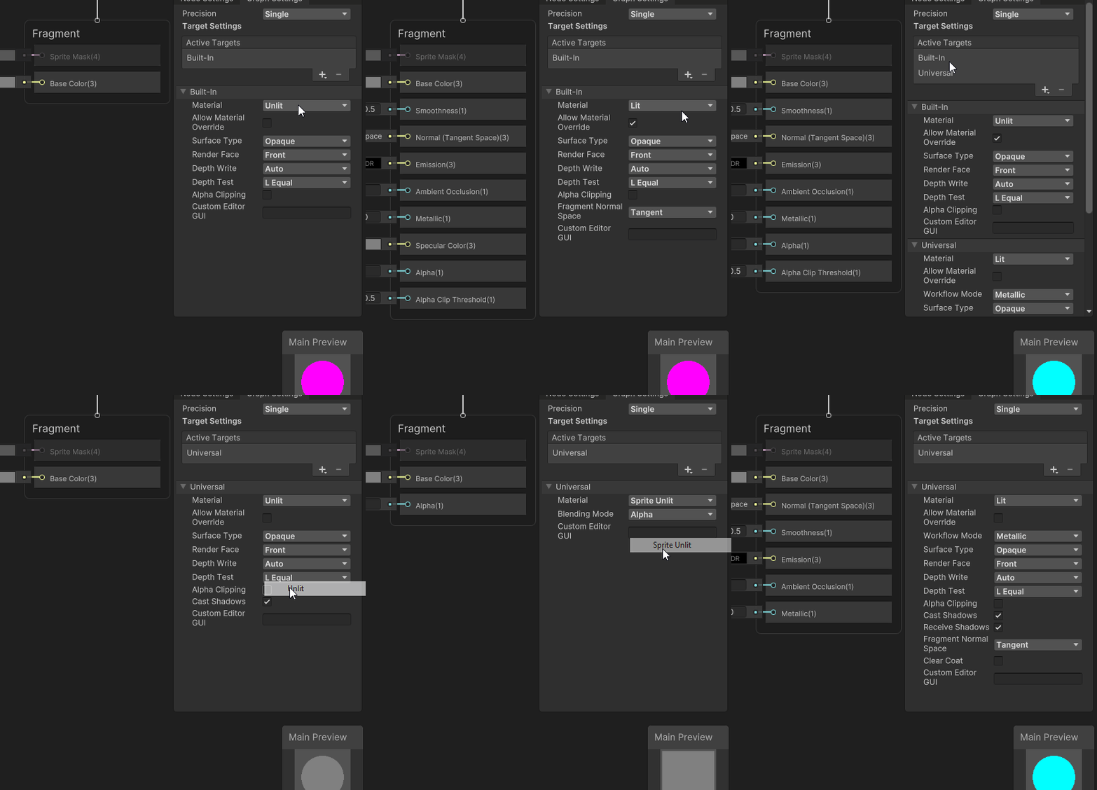
Shader Graph has over two hundred different nodes that can be used to create a shader; refer to Unity’s Node Library for a detail on all of the nodes.
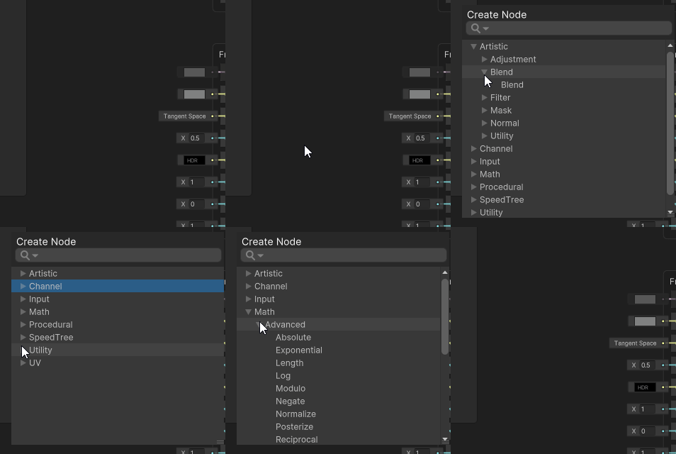
The nodes are organized by categories in the Create Node menu:
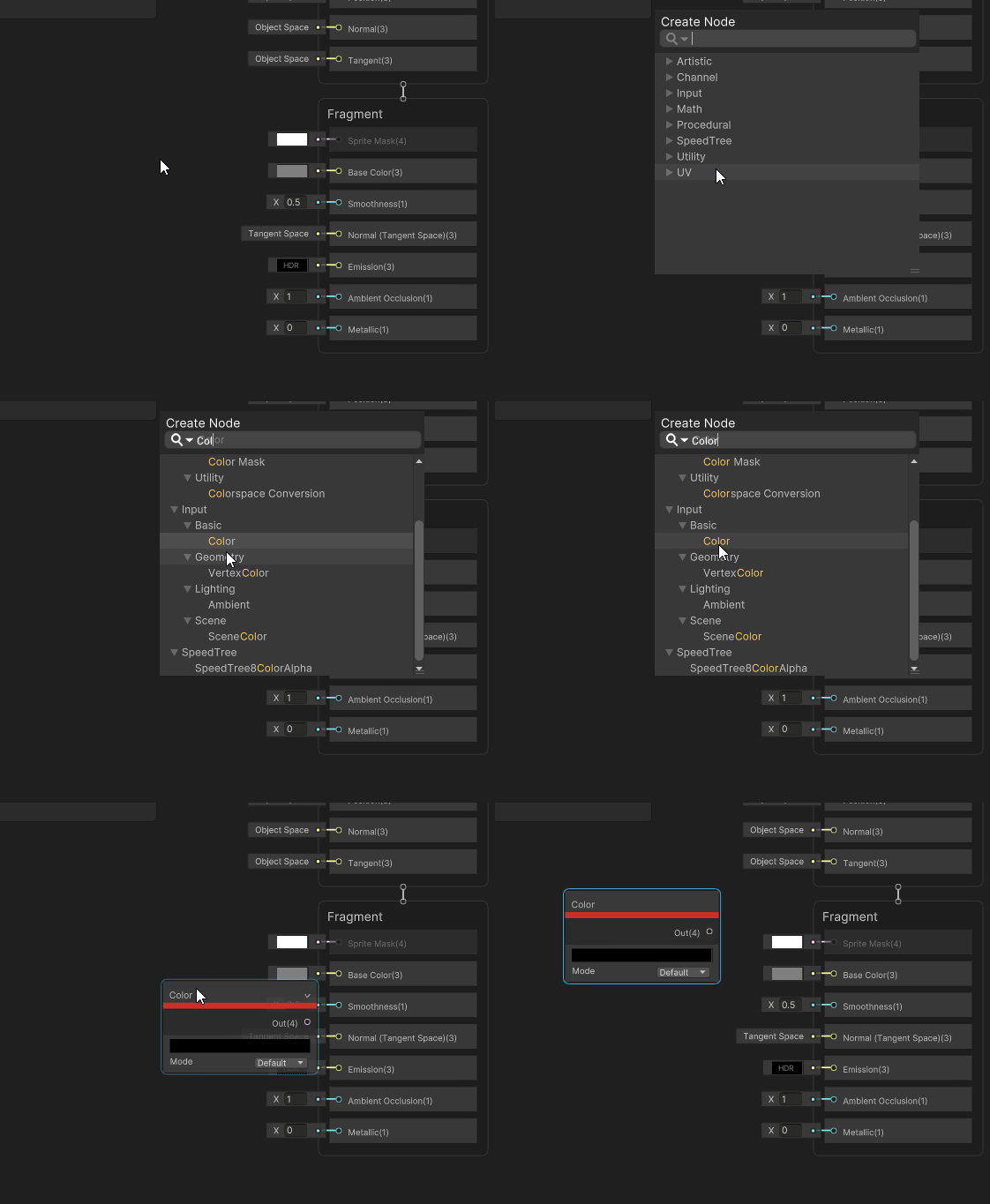
To access the Create Node menu, you can right-click in the Shader Graph view and select Create Node or press the spacebar. Nodes can be found by looking through the submenus or typing them in the search bar.
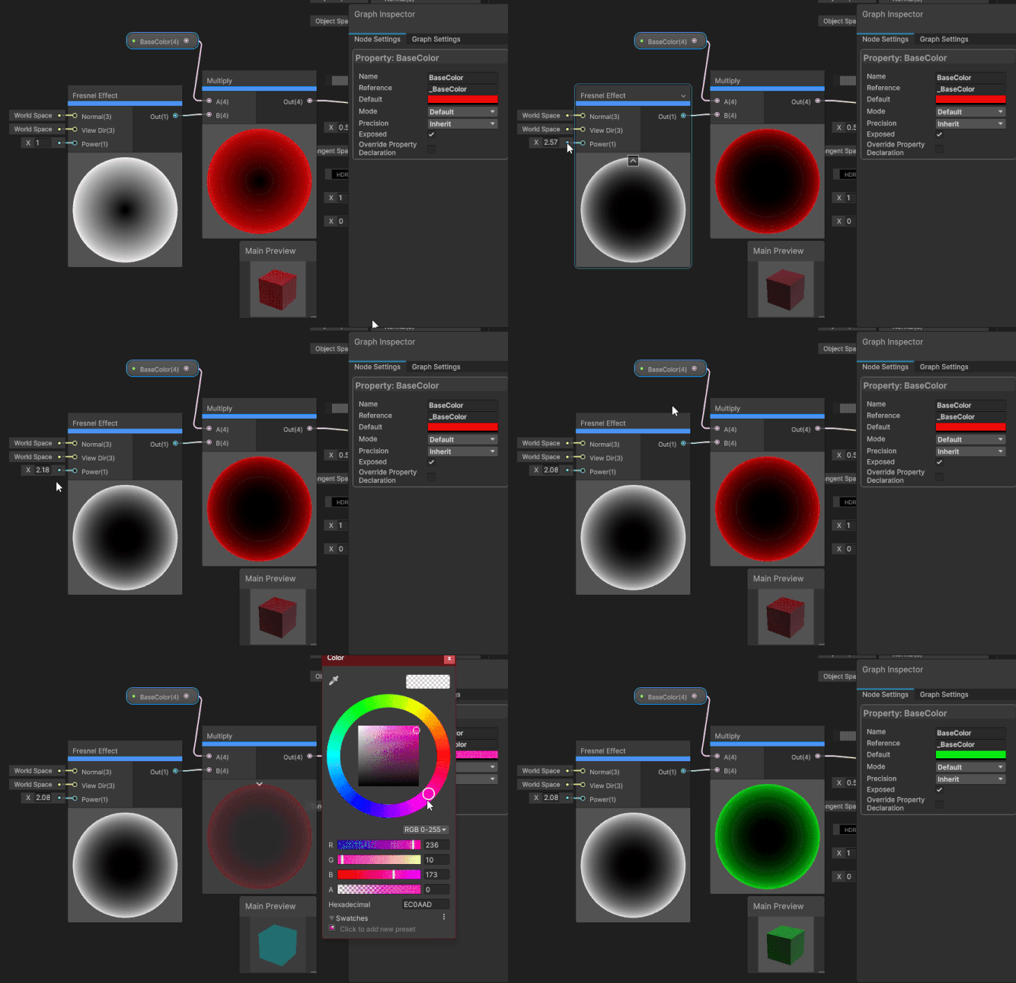
Nodes have input ports and output ports. The different ports accept different data types depending on the node. Not all nodes have an input port. For instance, the Block nodes have no output port.
Unity tried to make Shader Graph extremely user friendly — this also helps with the debugging of your effect. They tried to make it so you can see the results of an effect along the way as much as possible. You do not have to wait for the final output to be connected to see how things change.
The Shader Graph has seven main components to it. Let’s go over them so you can become familiar with these windows.
This is the Shader Graph window itself. It contains (listed in order by view precedence) the Toolbar, Blackboard, Graph Inspector, Main Preview, Master Stack, and Nodes.
You can zoom in and out with the scroll wheel, pan with the middle mouse button, and drag-select with and move items around with the left mouse button. To open this window, all we have to do is double-click on a Shader Graph Asset in the Project view.
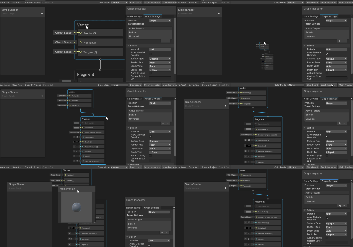
This is where we can add the properties and keywords. The Blackboard can be moved anywhere within the main view and is set in a manner that we can never lose it. It can be turned on and off.
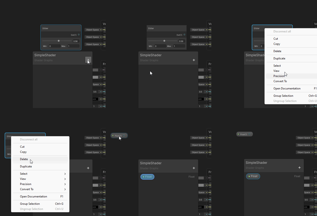
This is a preview of what the final output of the shader will look like. The main preview can be moved anywhere within the Main View and is set in a manner that we can never lose it. It can be turned on and off. You can select one of the inbuilt meshes to use or use a custom mesh (any mesh object that is in the project).
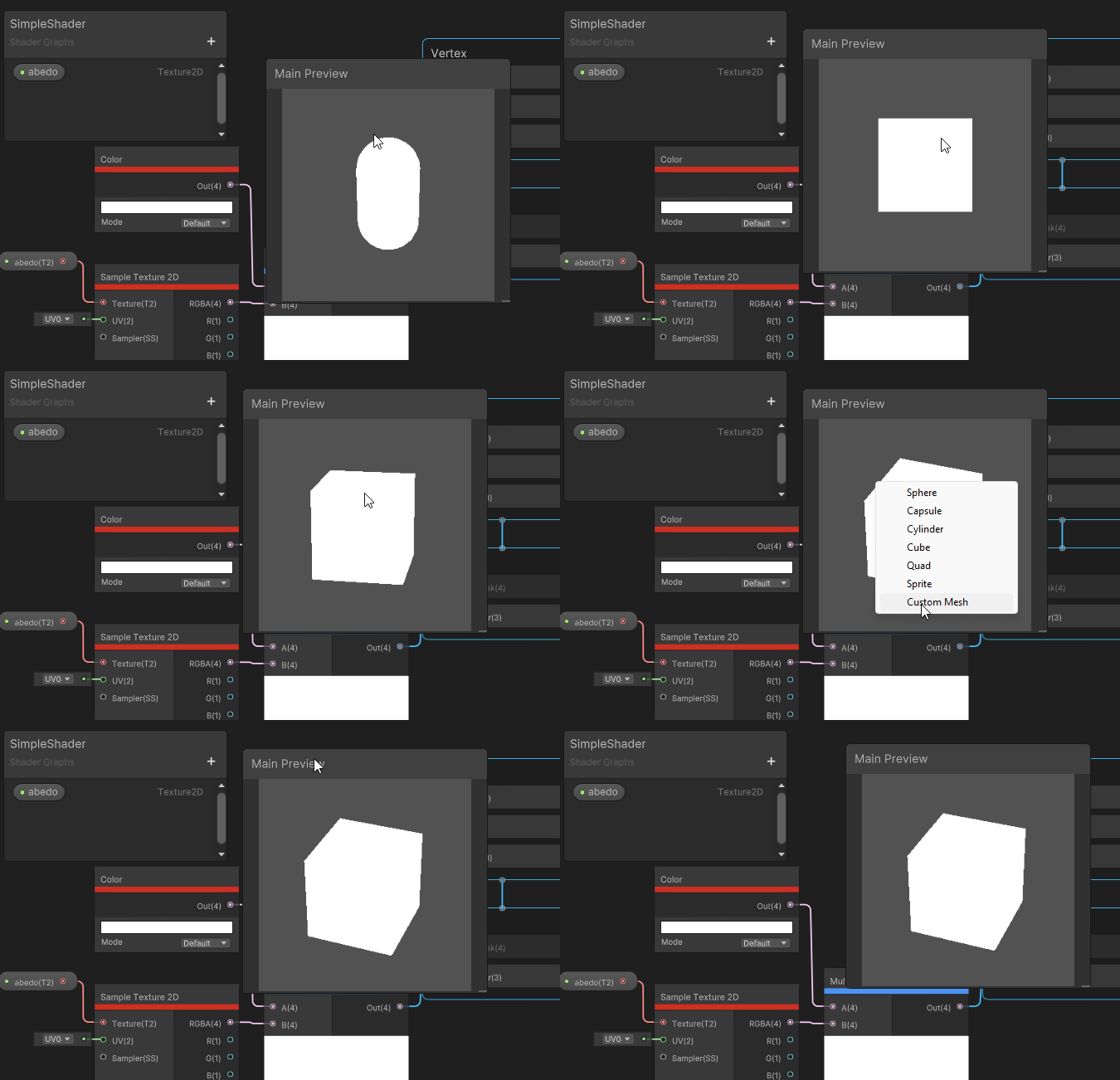
The nodes of the graph. This window can be moved anywhere within the main view, zoomed in and out, added and deleted.
The difference between this node and all the others is that we can not add or delete it. It will always be displayed above all other nodes.
The Graph Inspector contains the Graph Settings and Node Settings tab. The Node Settings tab changes depending on which node/block/parameter/keyword we have selected.
This window can be moved anywhere within the main view and is set in a manner that we can never lose it. It can be turned on and off.
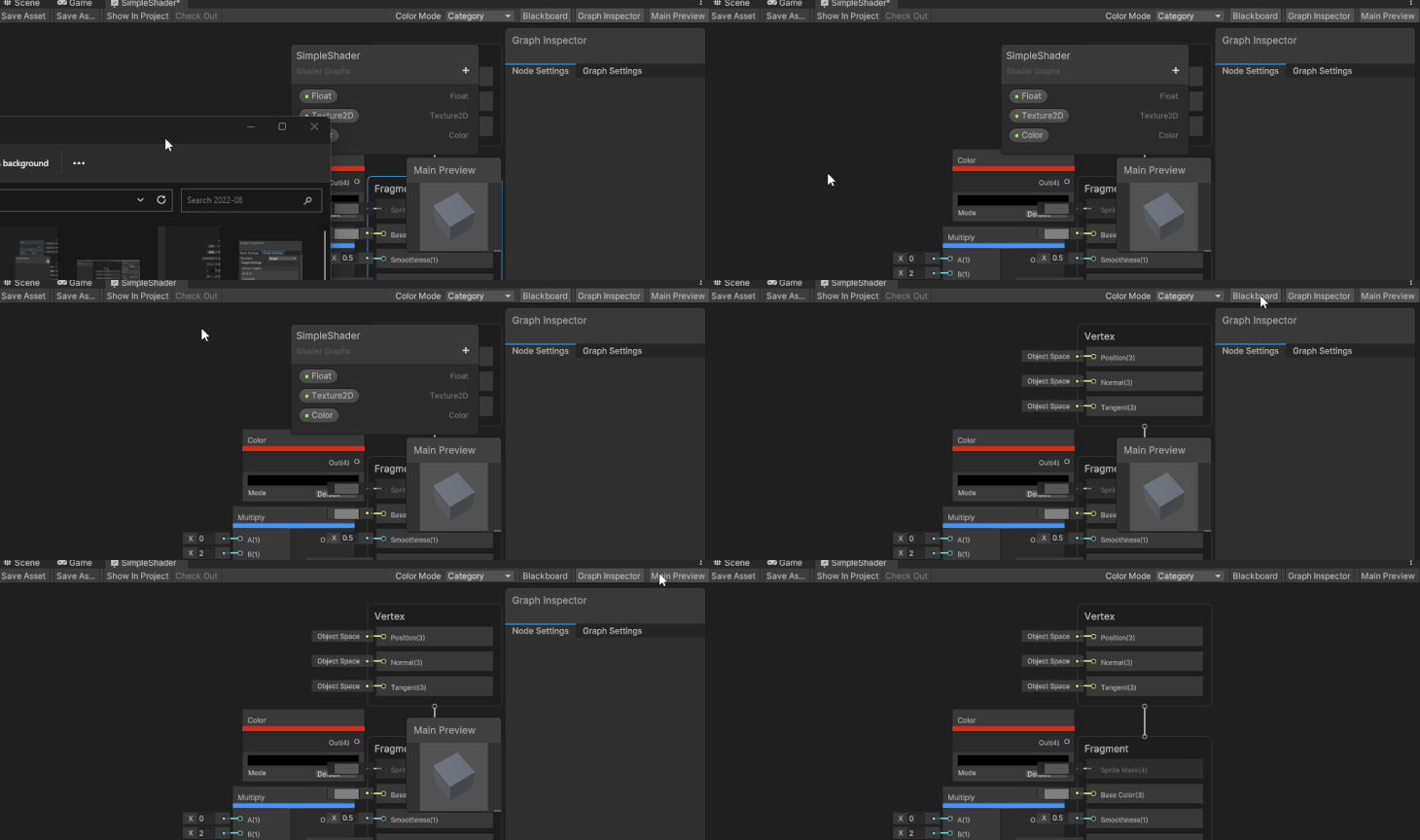
Permanent at the top of the window, the toolbar contains the File buttons on the left and the Color Mode selection.
The Shader Graph is packed full of useful features. These are a handful you’ll be using frequently; let’s see how you can take advantage of them.
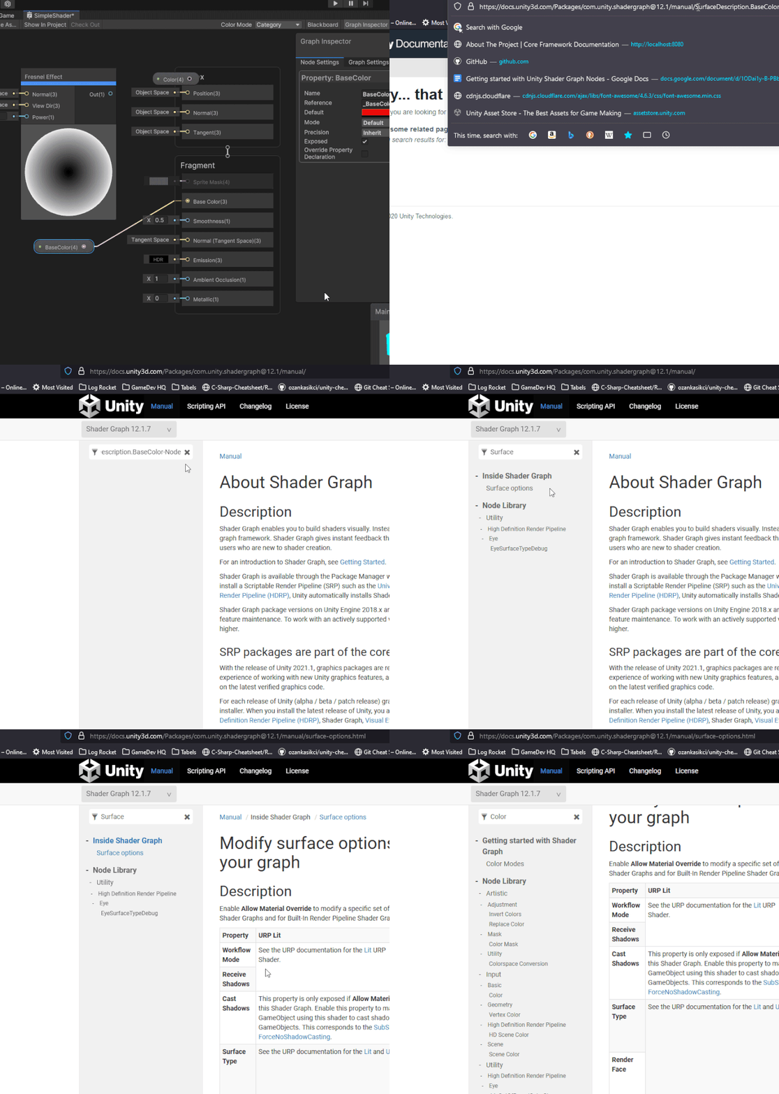
One helpful item is the ability to access the documentation straight from a node. With the node selected, press F1 on the keyboard.
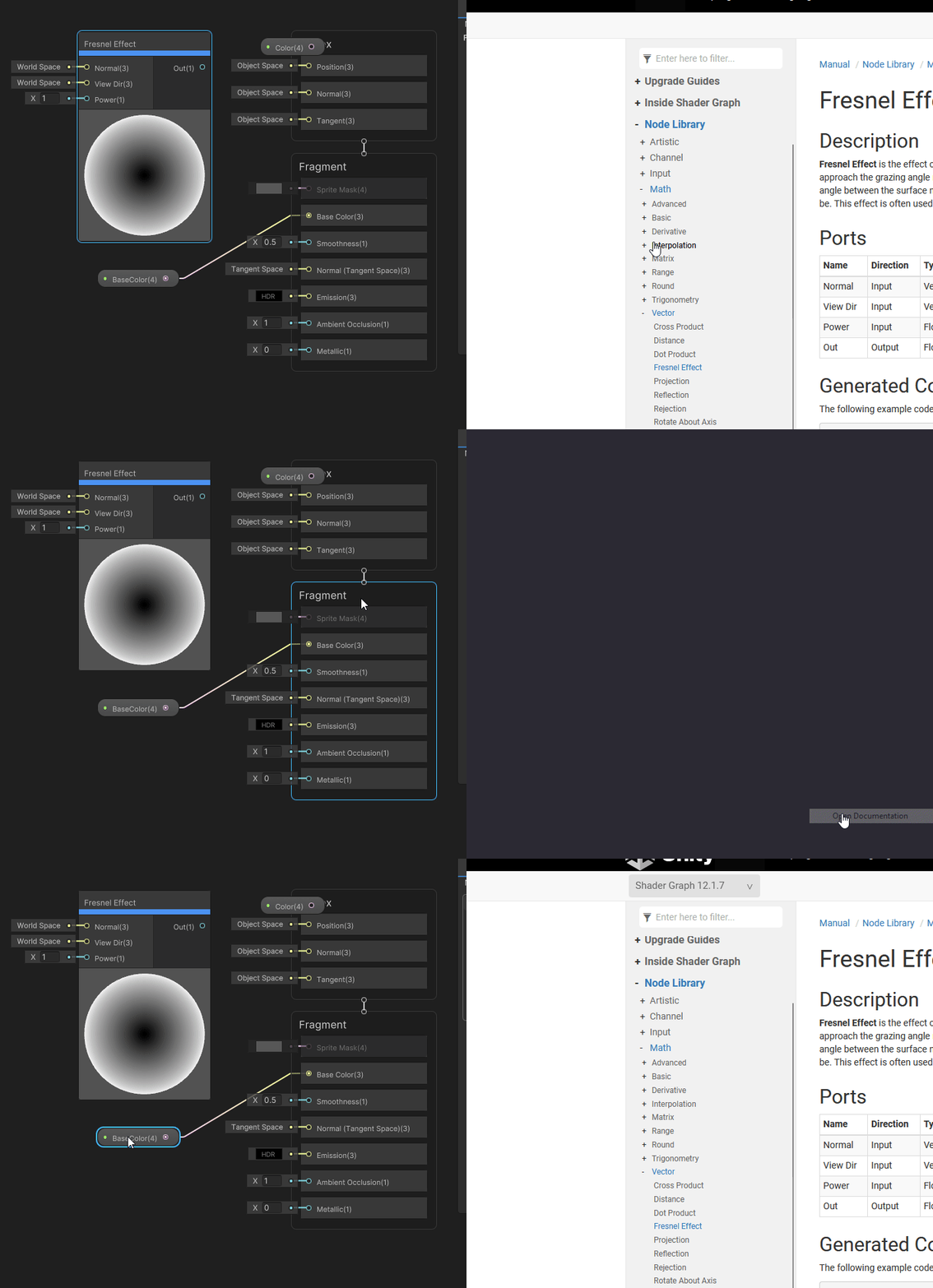
Please note that even though some of the others in the window have the same option, it does not connect all of the time. If you run into that issue, delete what is in the address bar after /manual/, and in the Filter Content, look for one of the keywords.
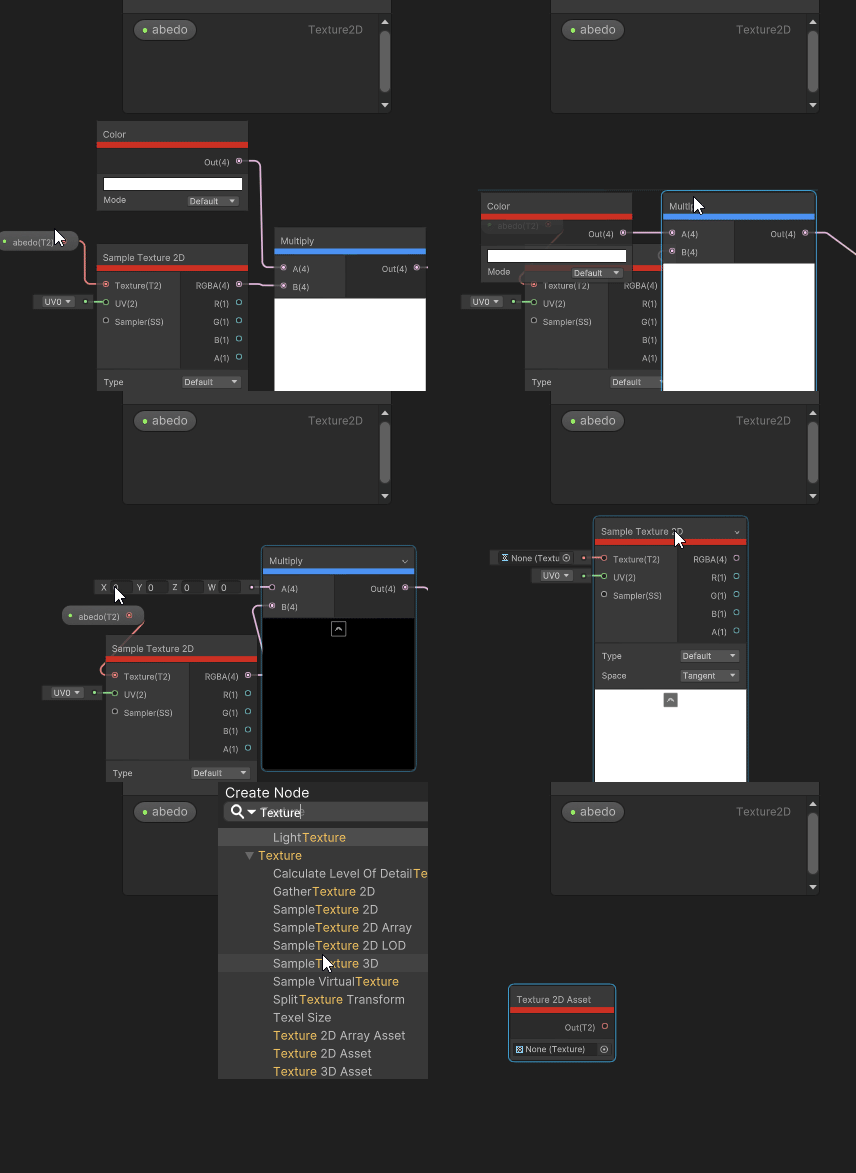
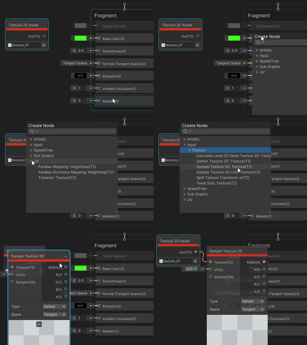
Connections between nodes are not allowed to be made between incompatible types. When you try, instead of making the connection, it will bring up the Create Node window that displays all of the nodes that has an input of the type that you are using as an output and an output of the type you are trying to use for the input.
For example, I have a Texture Asset that I want to use for the Base Color Block. The Texture2D Asset has an output Texture2D, but the Base Color takes an input of Vector3. When I try to connect the output of the Texture2D Asset to the input of the Base Color Block, I get a Create Node menu that has all of the nodes that have an input of Texture2D and an output that is compatible with a Vector3.
When I choose Input > Texture > Sample Texture2D, I get a new Sample Texture2D node that has a connection to the Texture2D asset node. Now all I need to do is pick which output of the Sample Texture2D I want to use (I will use the RPGA, which is a Vector4).
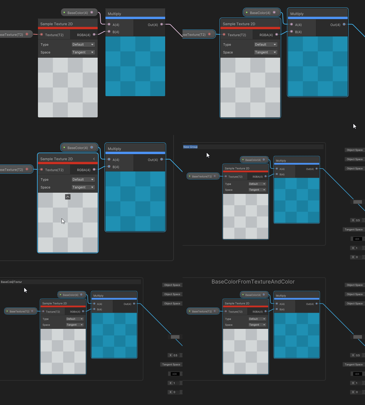
You can group nodes together by clicking a dragging to select a group.
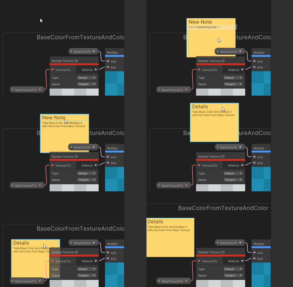
Notes that can be used to add details, a to-do list, comments, etc.
Take a group of nodes that perform a specific function and turn them into a Sub Graph. These Sub Graphs can be reused in other graphs like any other node. Find yourself repeating the same steps over and over in multiple shaders? Turn it into a Sub Graph.
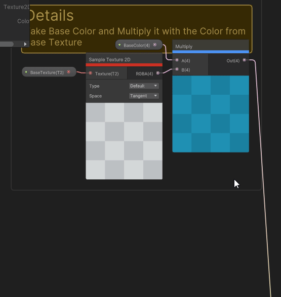
Notice how it left the properties in the main graph. Double-clicking on the Sub Graph opens it in a new Sub Graph window. The properties got duplicated, but the defaults changed back to Unity defaults.
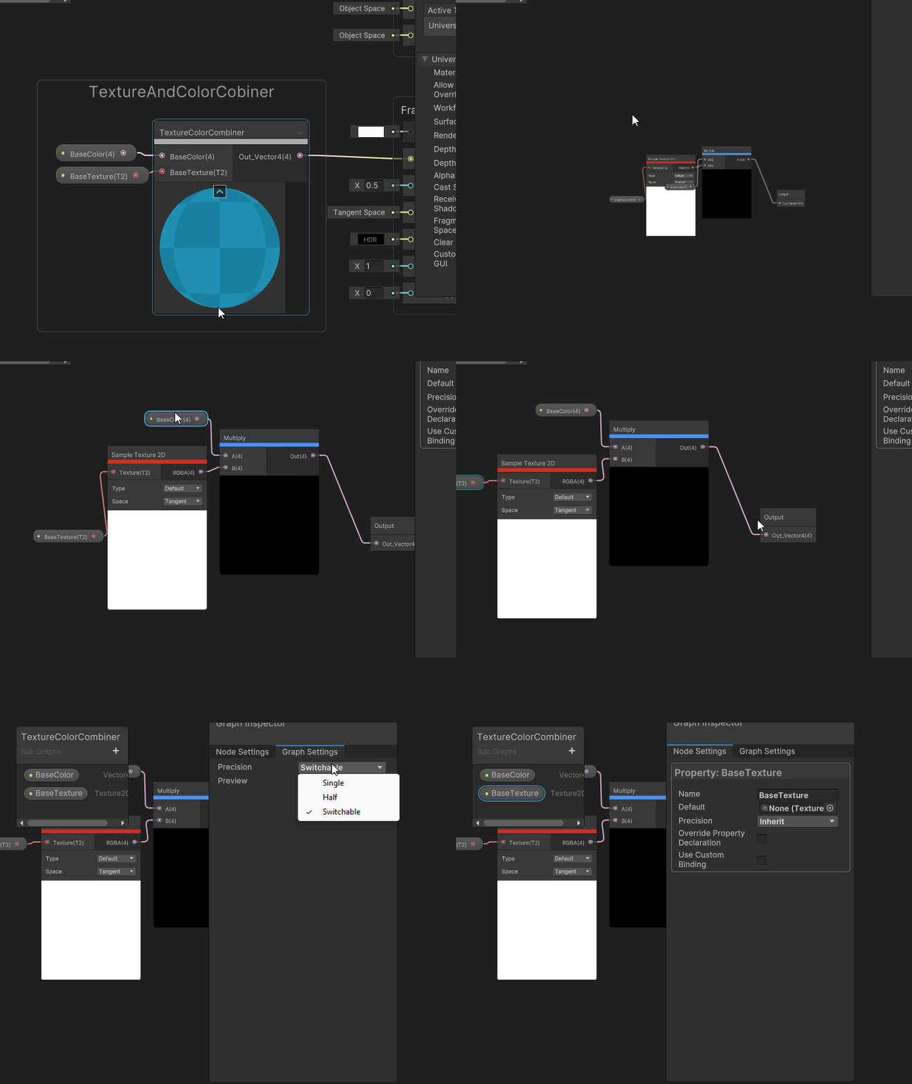
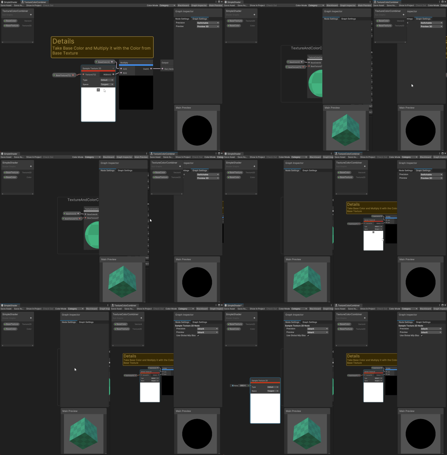
You are able to have multiple Shaper Graphs open at one time. Each Shader Graph or Sub Graph will open in its own Shader Graph window. These windows can be moved around just like any other window in Unity. You can even copy nodes from one Shader Graph to another.
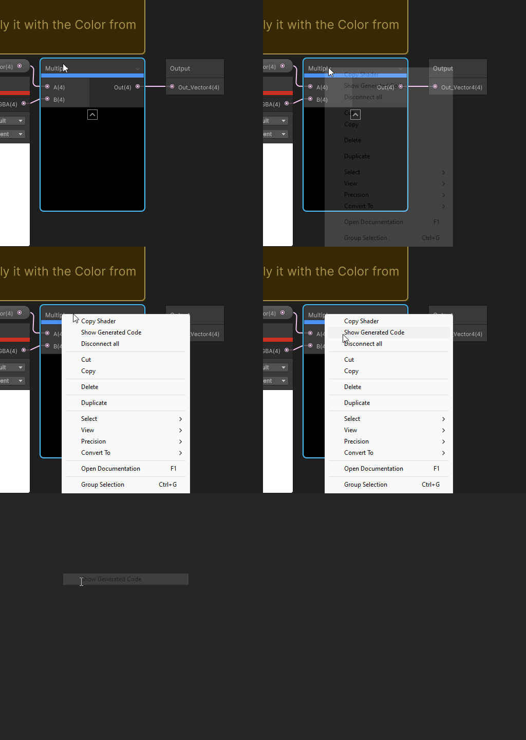
In addition to the node library documentation for a node, you can generate the code for each node and select Show Generated Code. This will open the code for that node in your code editor.
You can also view the code for the entire shader by selecting it in the Project view and selecting one of the view/show code buttons.
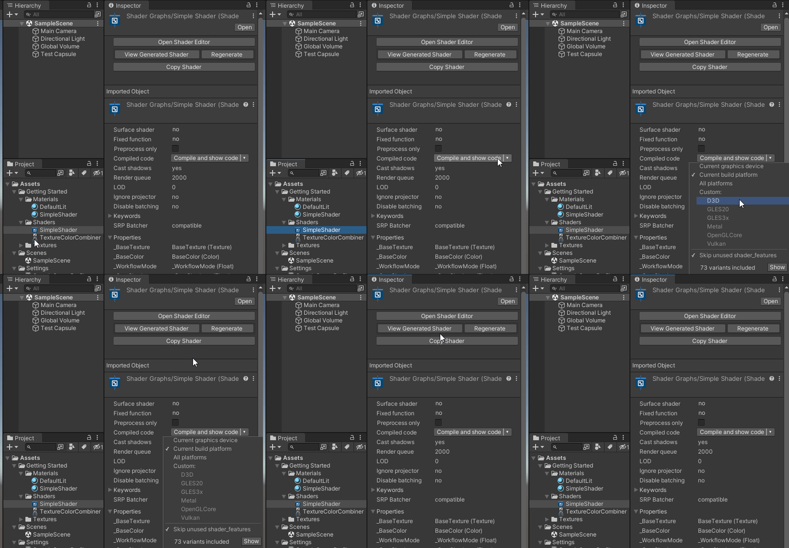
Now we have everything needed to create a simple shader. Let’s make a Lit shader that can be used in both the Built-In and URP that has a color that can be set in the Inspector. If you want to, include HDRP just ensure that you have HDRP added in your project.
To start, create a Shader Graph asset and open it in the Shader Graph window. I have already created a Lit Shader Graph, so I just double-click on it to open it. If you have not created one yet, right-click > Create > Shader Graph > SRP you want to use > type of shader.
In my case, I am going to use URP > Lit Shader Graph.
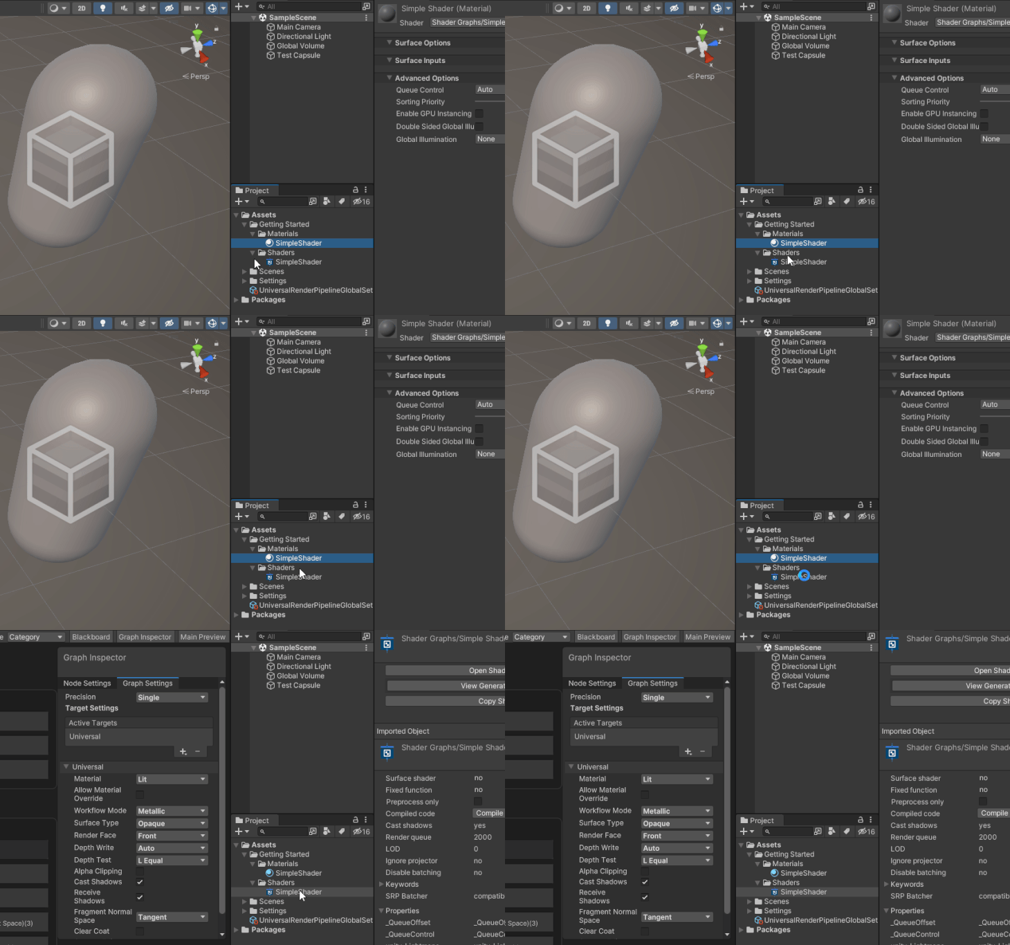
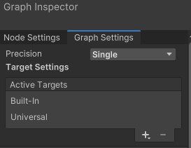
In the Graph Settings, make sure that the Shader Graph has all the targets listed. In my case, I use Built-in and Universal (feel free to use just one, e.g., Universal). Then make sure each of them are set to Lit.
Next, create a new node. I want to be able to change the color, so I need a color node.
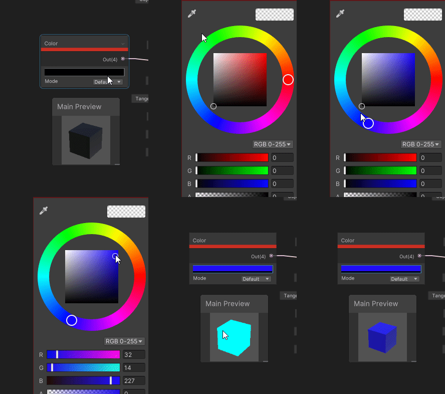
Now the Color node needs to be connected to the Master Stack. To do this, I clicked on the Output of the Color node and drag it to the Input of the Base Color. Notice that the connection updated the Main Preview.
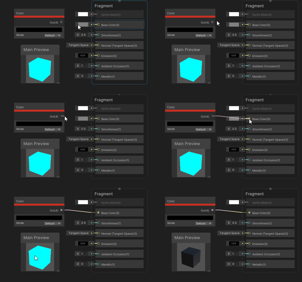
Next, I changed the output color of the Color node to a blue. Notice that this was updated in the Main Preview, too.
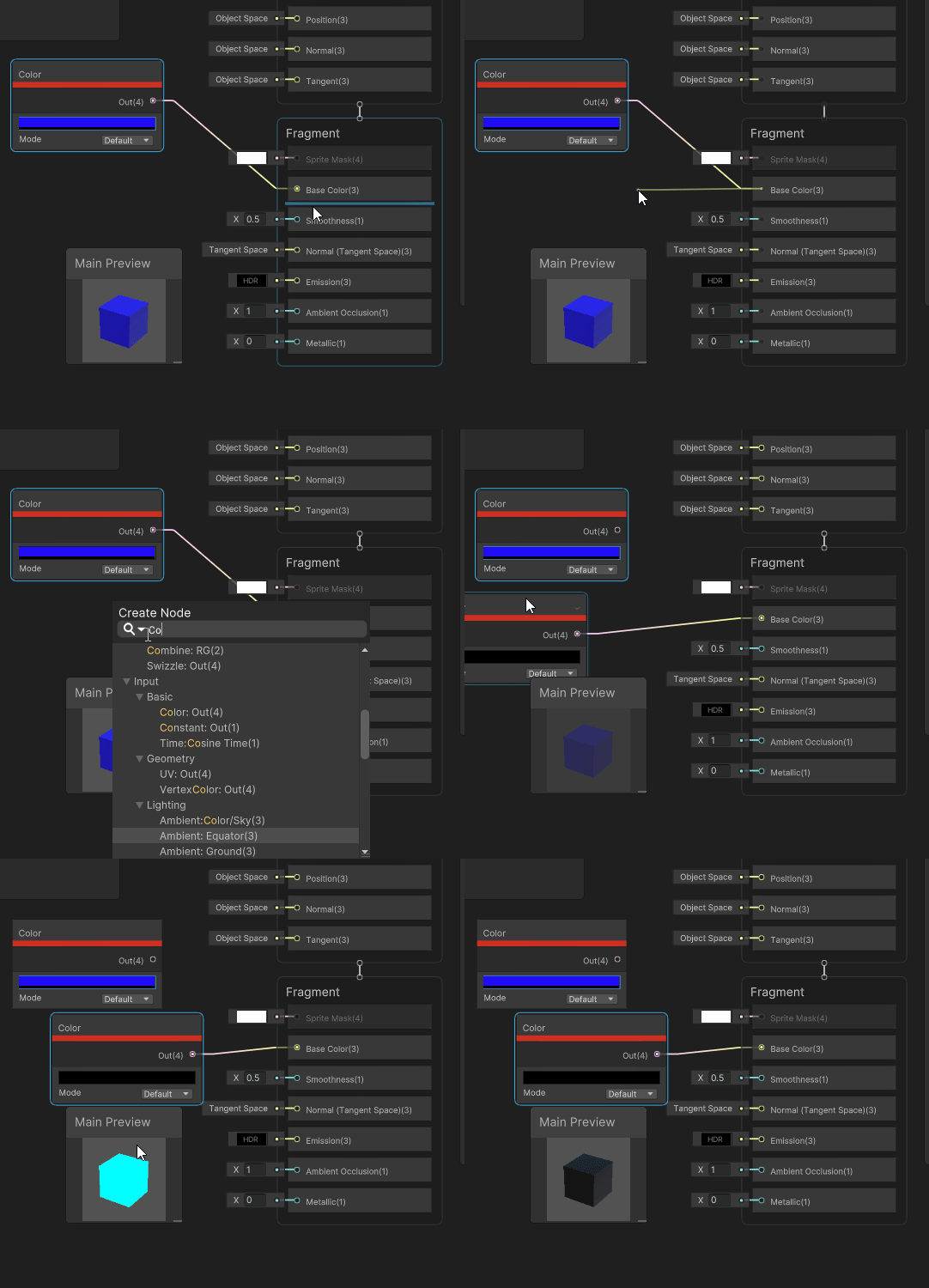
Note that I could have done the creation of the node and connected it to the Base Color Block in one step. To do this, click on the output of the Base Color Block and drag to an empty space in the Shader Graph main window.
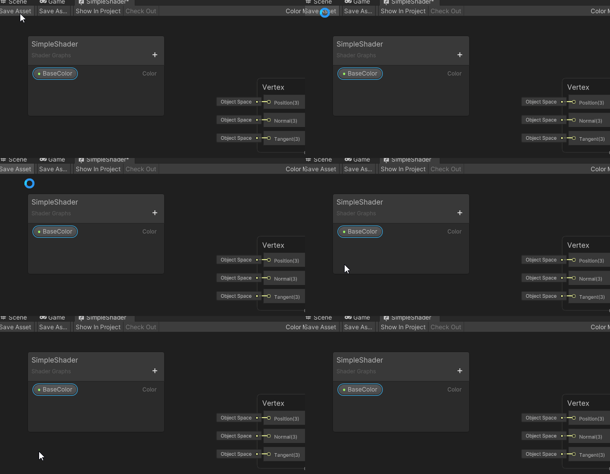
For this to be used in my scene, I have to make sure to save the graph.
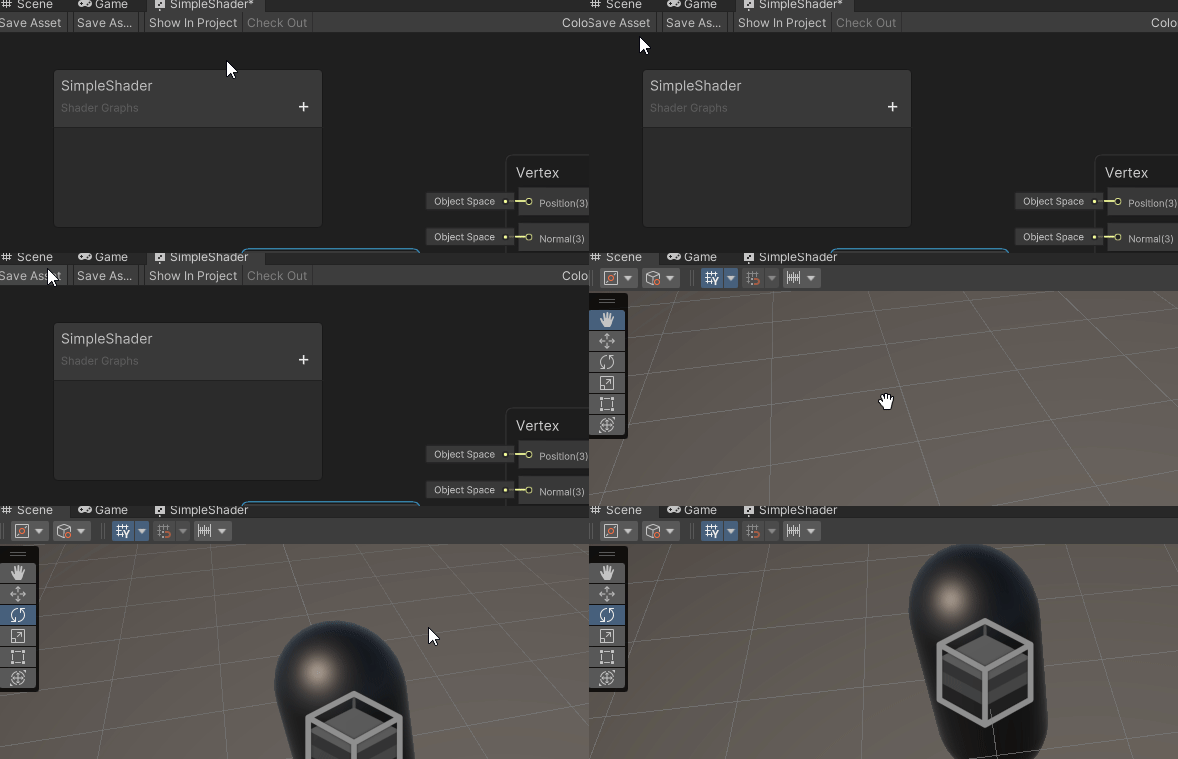
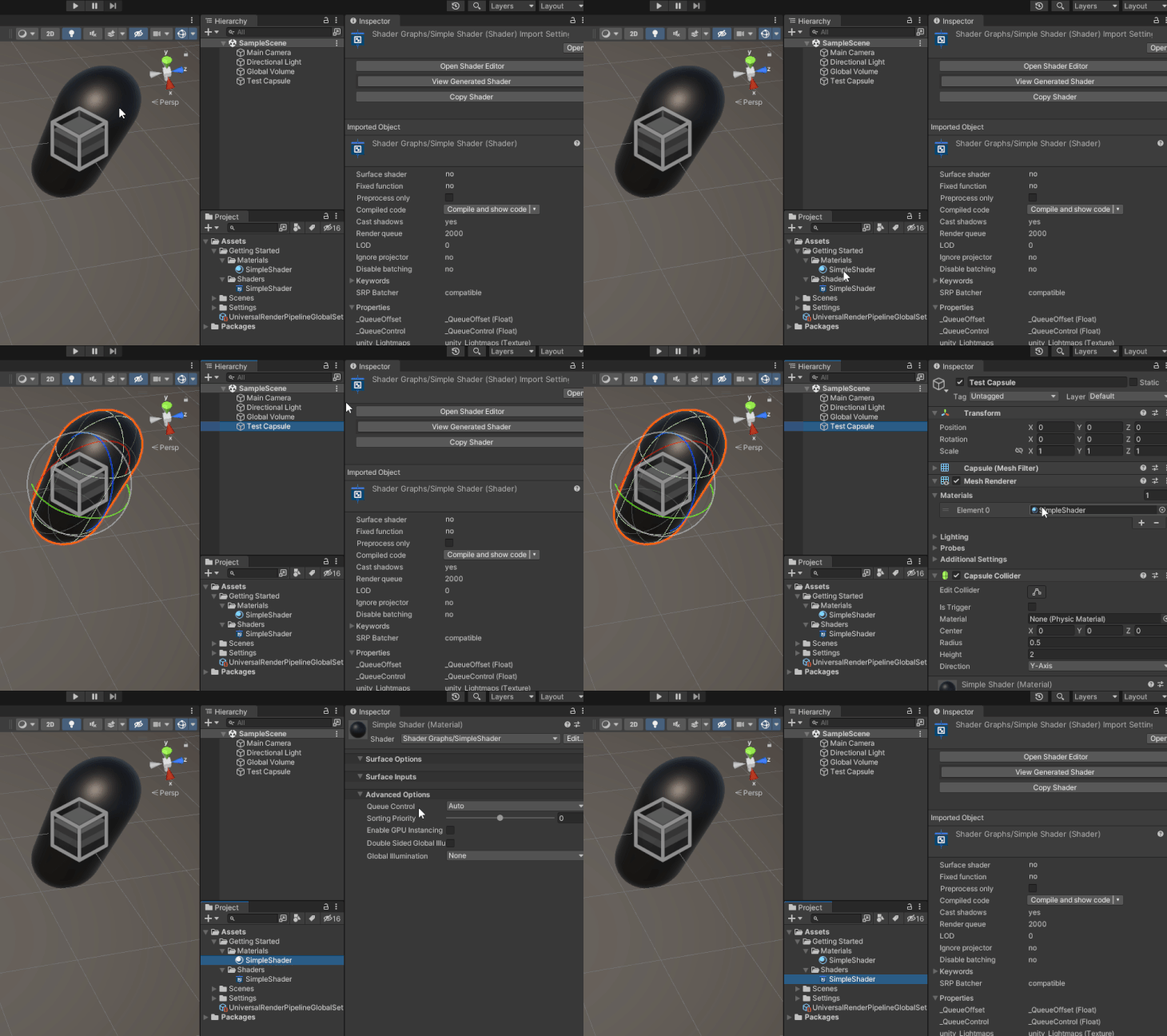
Of course, if it doesn’t appear on my object in the scene, then the first step is to make sure that the Render Component of the GameObject is using a Material that is using the shader.
The last requirement Is to make this color settable in the Inspector. For this, I need a property.
I can create a property in the Blackboard and add a new Color Property.
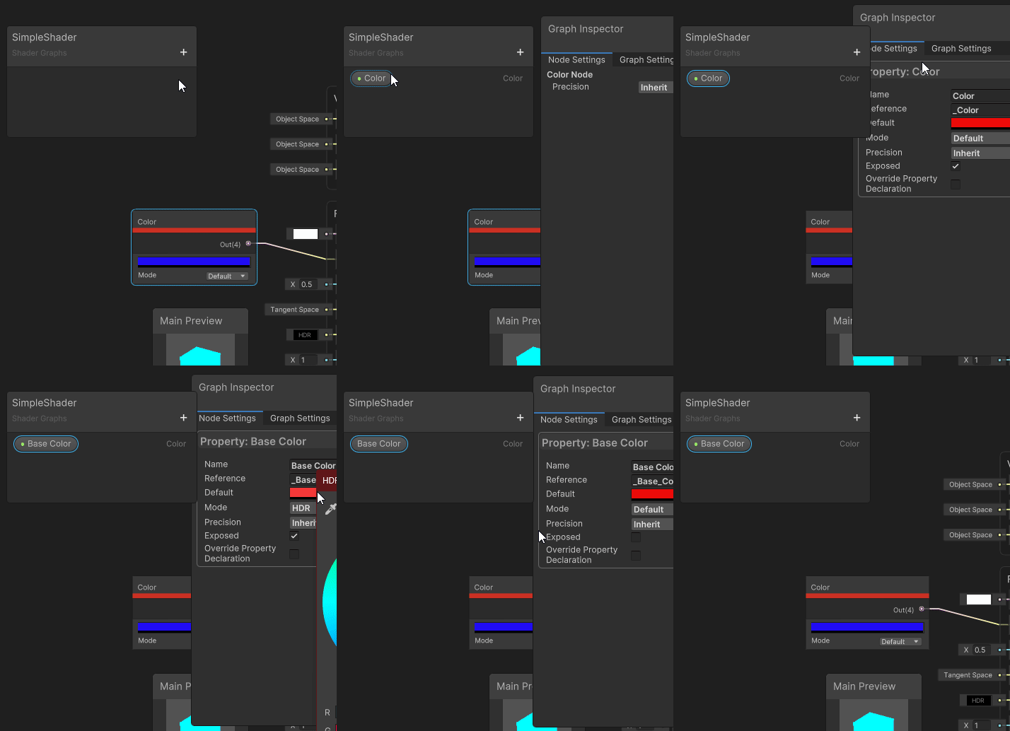
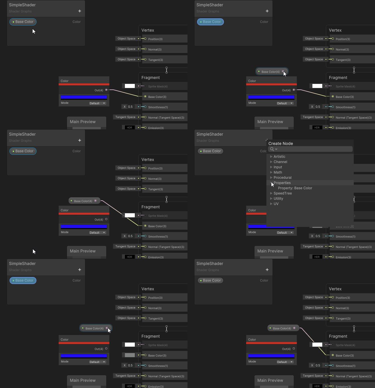
Then either drag and drop it or use the Create Node menu and select it in the Properties submenu.
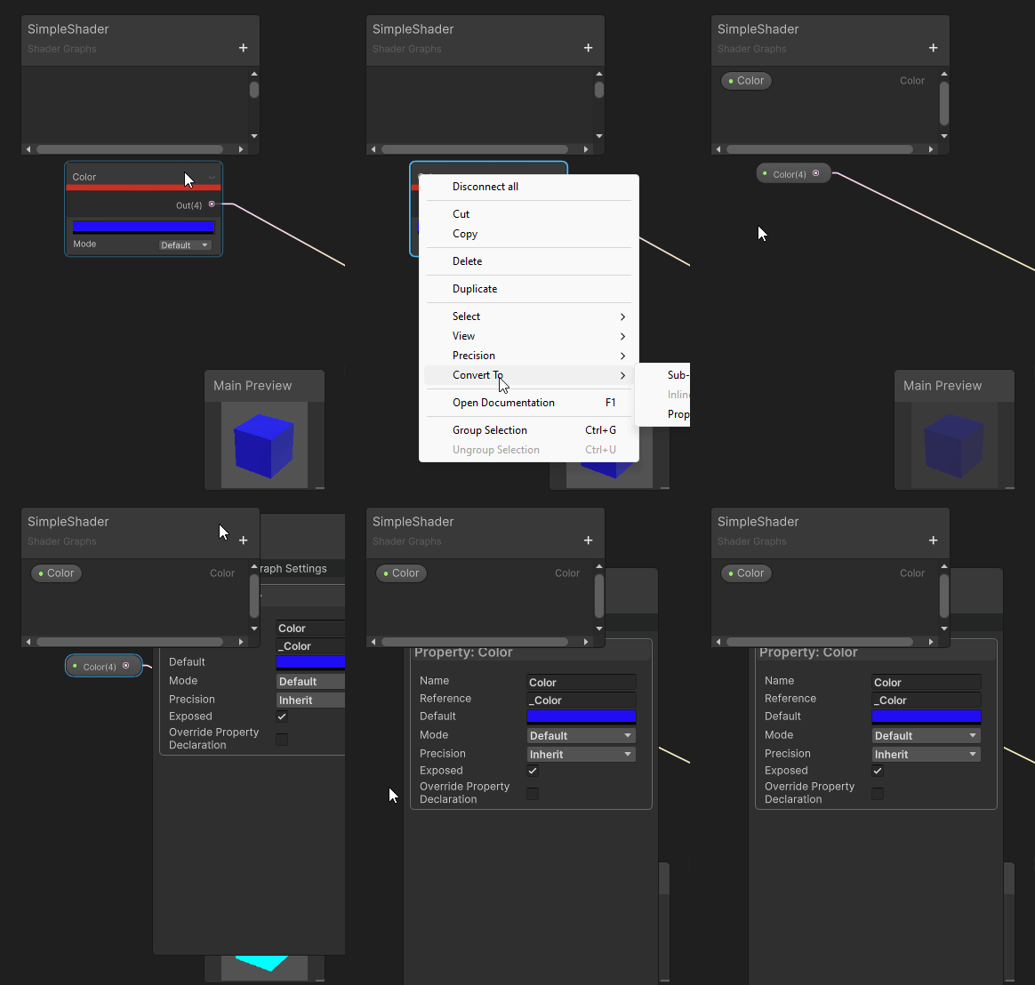
I can also simplify this step and convert the Color node that is already in the graph to a property.
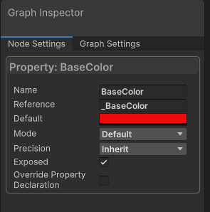
The most important thing to note is the Node Settings of the property. In order for it to be exposed in the Inspector, we need to make sure the Exposed setting is set. The other setting that we need to take note of is the Reference setting; this is the name to use in C# scripts.
Don’t forget to save the asset.
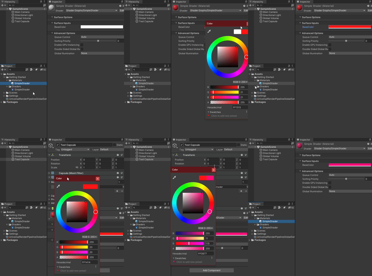
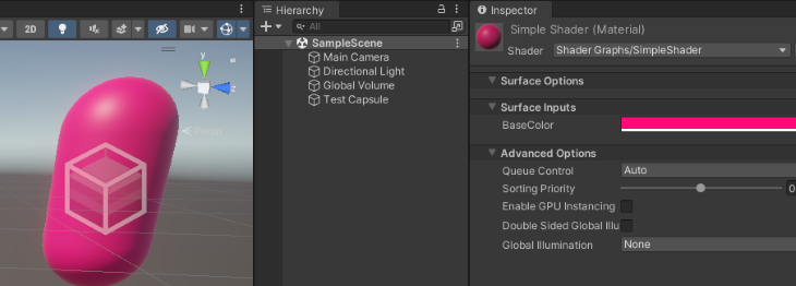
Now we can change the color in the Material’s Inspector.
This is a very simple shader, so let’s take a look at a side-by-side comparison of the code.
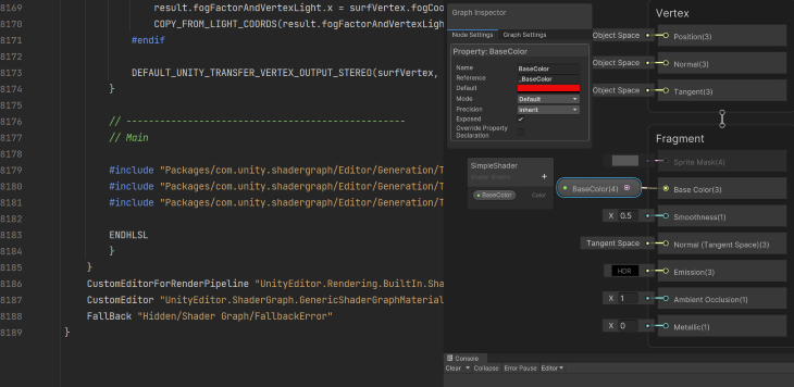
Using Shader Graph is definitely easier and quicker. Technically, I got two shaders because it works on two different render pipelines.
In this section, I will try to show some of the common things that shaders are used for and the nodes that are used to make them. I will show different nodes in each example, but I will not be able to go through all 200+ nodes that are available.
If you want to know what a different node does that I don’t show here, I suggest checking the documentation, adding it to your Shader Graph, and seeing how it works. Remember: most nodes have their own preview, so you do not have to connect it to anything to see its effects.
Most of these nodes are reusable and can be connected together, so I will convert them to Sub Graphs, and the effect can be added to any other Shader Graph. Every example will use the Property node (probably more than one). The Property node works the same as its base type node with the difference being that the Property node can be easily accessed from C# scripts and the Material’s Inspector.
One of the most basic things that you will want to achieve is to have a texture that is associated with your model and have it rendered as a color. Typically, the base texture is combined with a color and then applied to the final output. Both the texture and color are usually settable from within the Inspector.
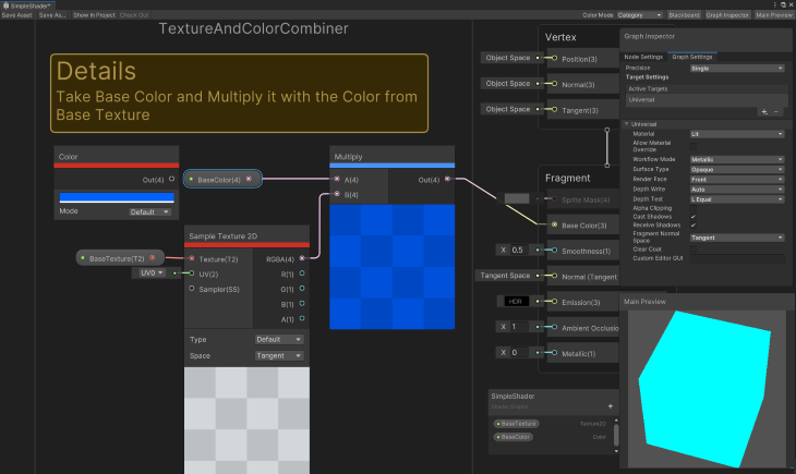
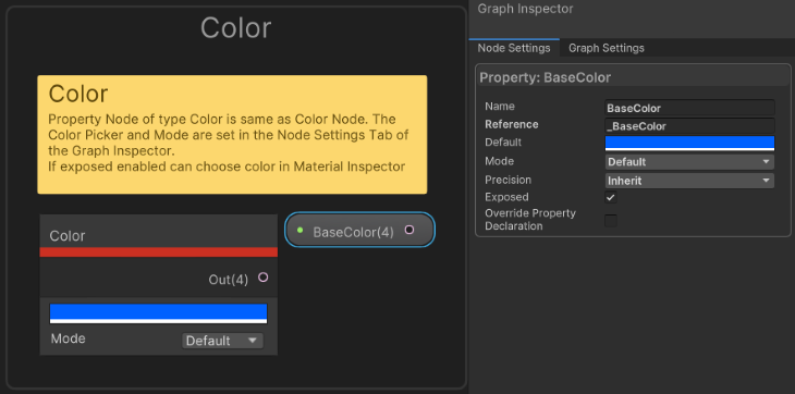
Color outputs a Vector4 representing an RPGA value. The Mode is Default or HDR.
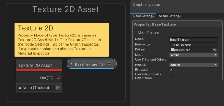
Allows you to select a Texture2D from the project’s assets. Used in conjunction with Sample Texture2D [LOD] node types. Allows a Texture2D to be loaded once and sampled multiple times.
The Texture2D property provides two additional settings not available with the Texture2D Asset mode:
If the Texture is not set, then it outputs a blank texture.
You can choose White, Black, Grey, Normal Map, Linear Grey, or Red.
To use Tiling and Offset, set to false in order to manipulate scale and offset separately, used from other texture properties like in Split Texture Transform Node | Shader Graph | 12.1.7.
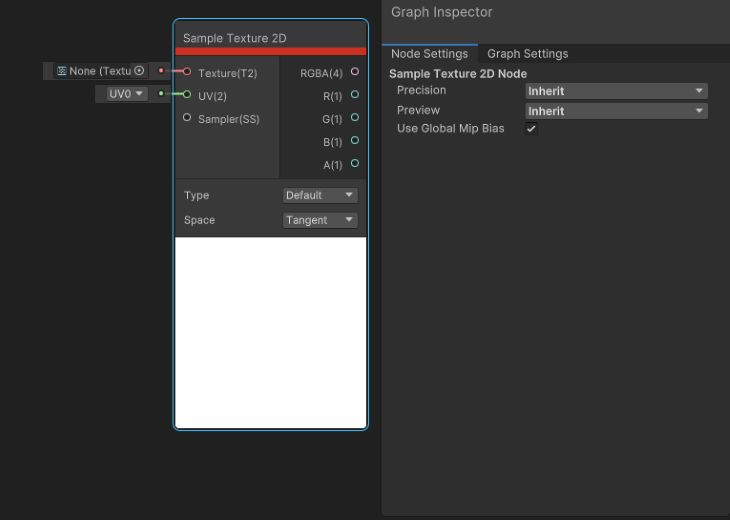
Sample Texture2D takes a Texture2D and returns a Vector4 color (RGBA). This can only be used in the Fragment Shader stage. For the Vertex Shader stage, use Sample Texture2D LOD node instead.
The settings Node Settings > Use Global Mip Bias enable the automatic global mip bias (set during certain algorithms to improve detail reconstruction) imposed by the runtime.
Node Settings > Preview: Inherit, Preview 2D, and Preview 3D are the type for the Preview area.
The texture type is Type: Default or Normal, and the space of the normal can be Tangent or Object. (Type must = Normal).
These are Sample Texture2D’s inputs:
And its outputs:
The Preview is a visual representation of what is output in (RBGA).
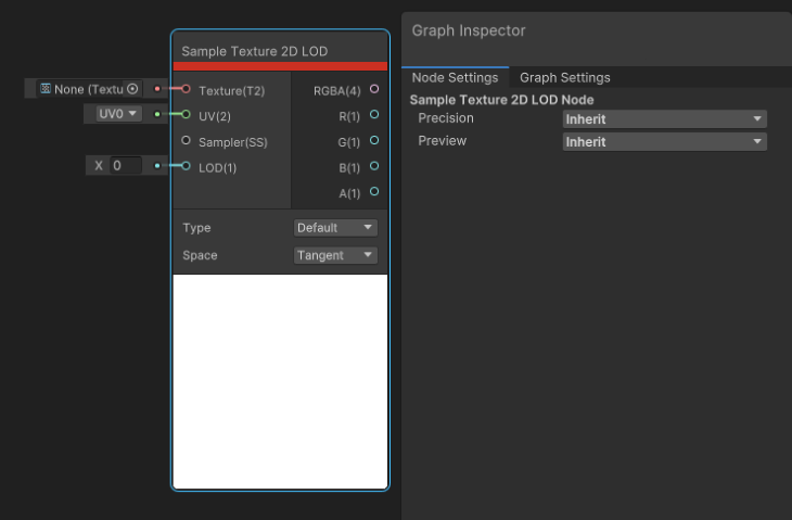
Sample Texture2D LOD takes a Texture2D and returns a Vector4 color (RGBA). This is only useful for the Vertex Shader stage. Some platforms (unsupported) may return opaque black instead.
Some settings to remember:
Sample Texture 2D LOD’s inputs:
Sample Texture2D LOD outputs:
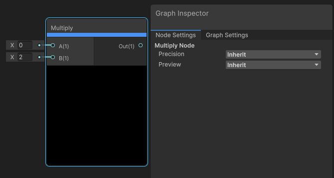
As the name suggests, the Multiply node multiplies input A by input B.
Multiply inputs:
Multiply outputs:
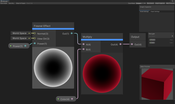
For this, we’ll build a rim light that has a Color and Power exposed in the Inspector.
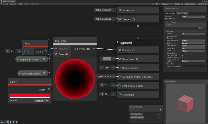
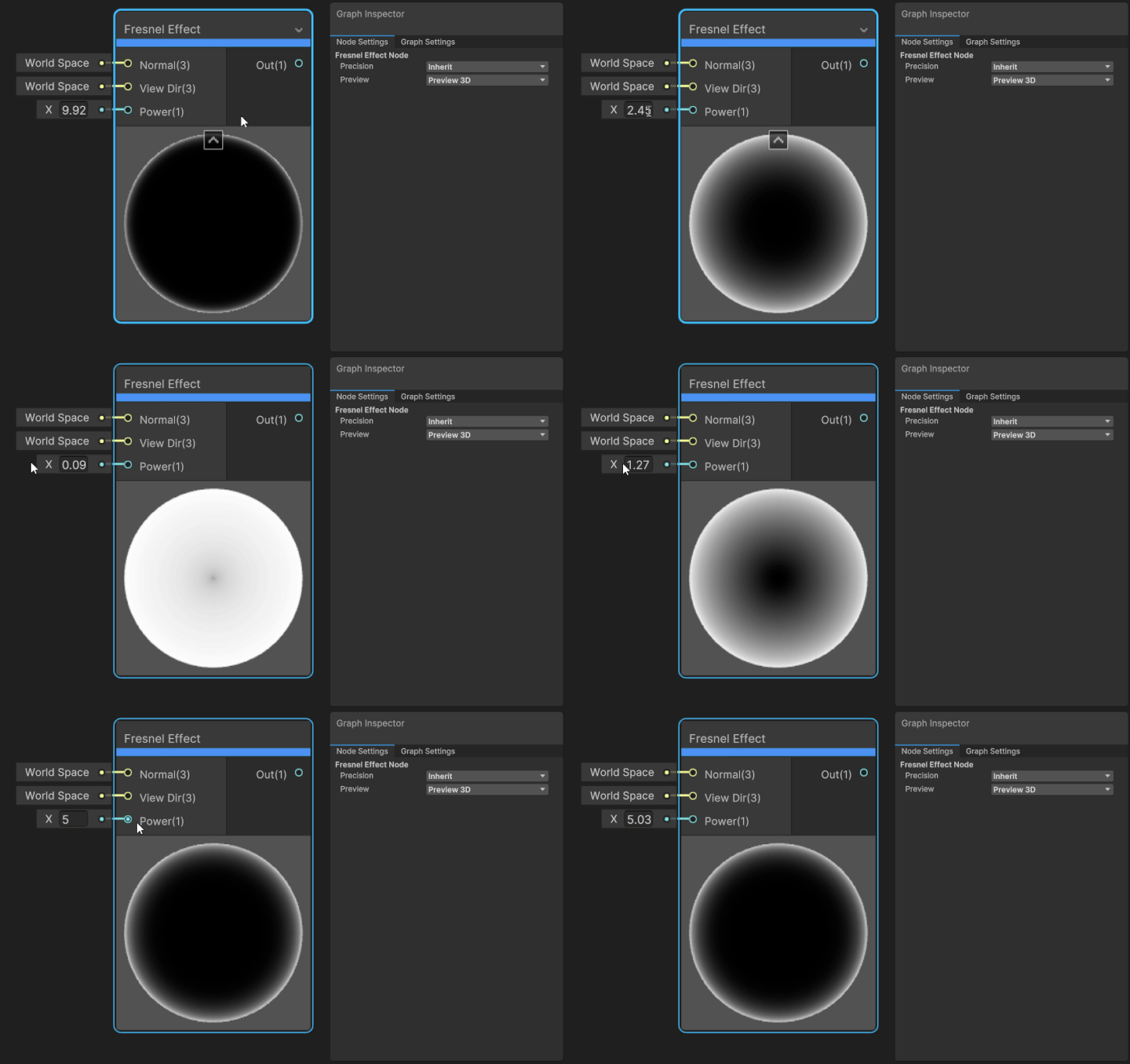
This node approximates a Fresnel Effect by calculating the angle between the surface normal and the view direction. This is often used to achieve rim lighting, common in many art styles.
Inputs:
Outputs:
This is a really cool effect that is used all the time. Some examples are bringing a game object into/out of a scene, destroying things that are on fire, or in a character editor changing the character (you dissolve the old character out and a new character in).
You can increase the DissolveScale while decreasing the DissolveAmount and you can get an interesting effect.
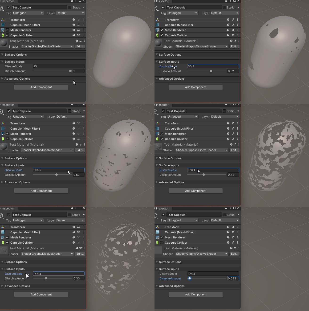
Be sure to enable Alpha Clipping in the Graph Settings and set the Alpha Block to 0.5.
If you want the inside of the model to render, set Render Face to Both, else set to Front.
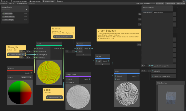
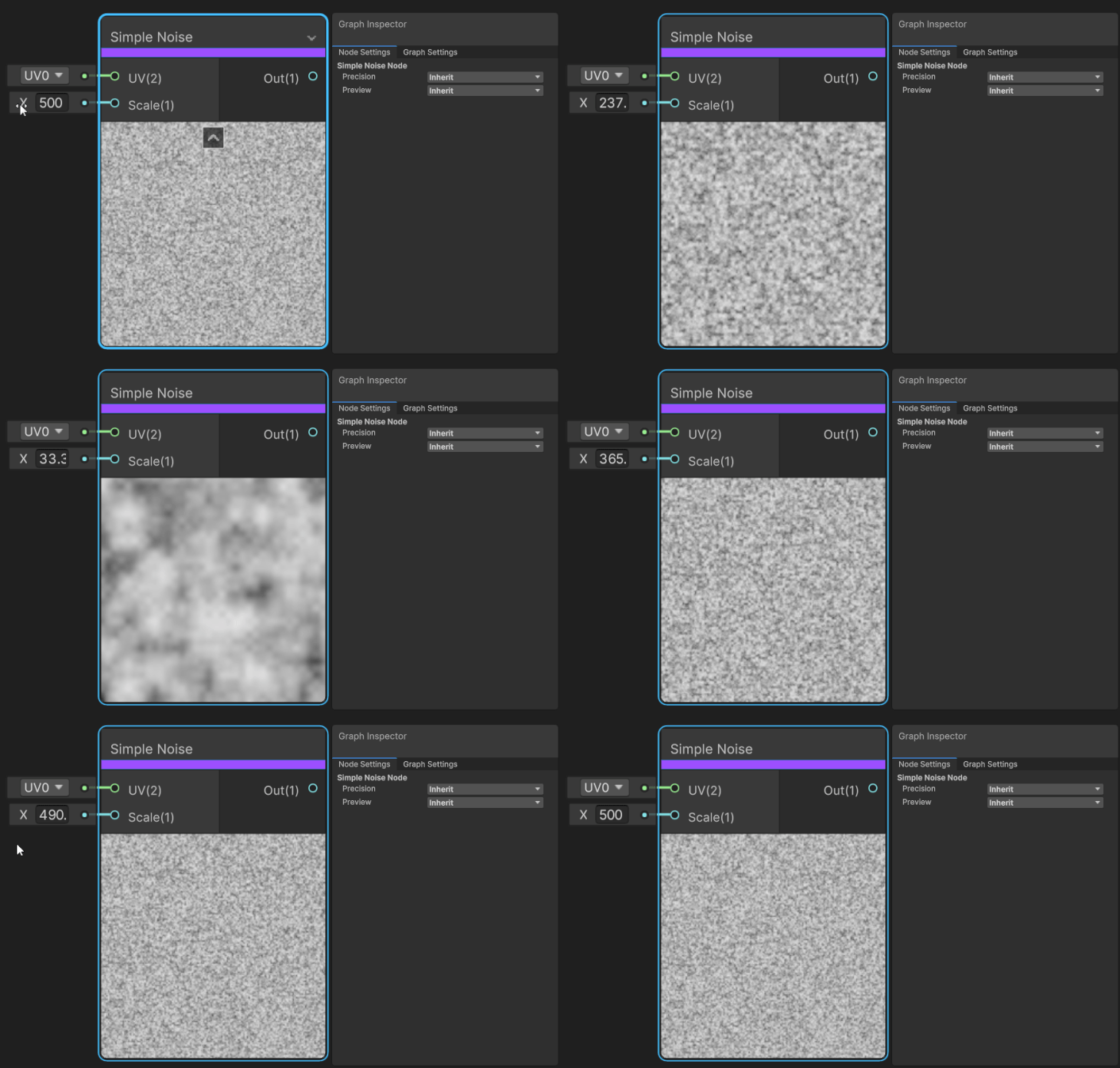
Simple Noise generates a Value Node based on the UV Input scaled by the Scale Input. There are a couple of other noise nodes that can be used depending on the type of noise you want (e.g., the Gradient Noise Node generates Perlin noise, and Voronoi Node generates Worley noise).
Inputs:
Outputs:
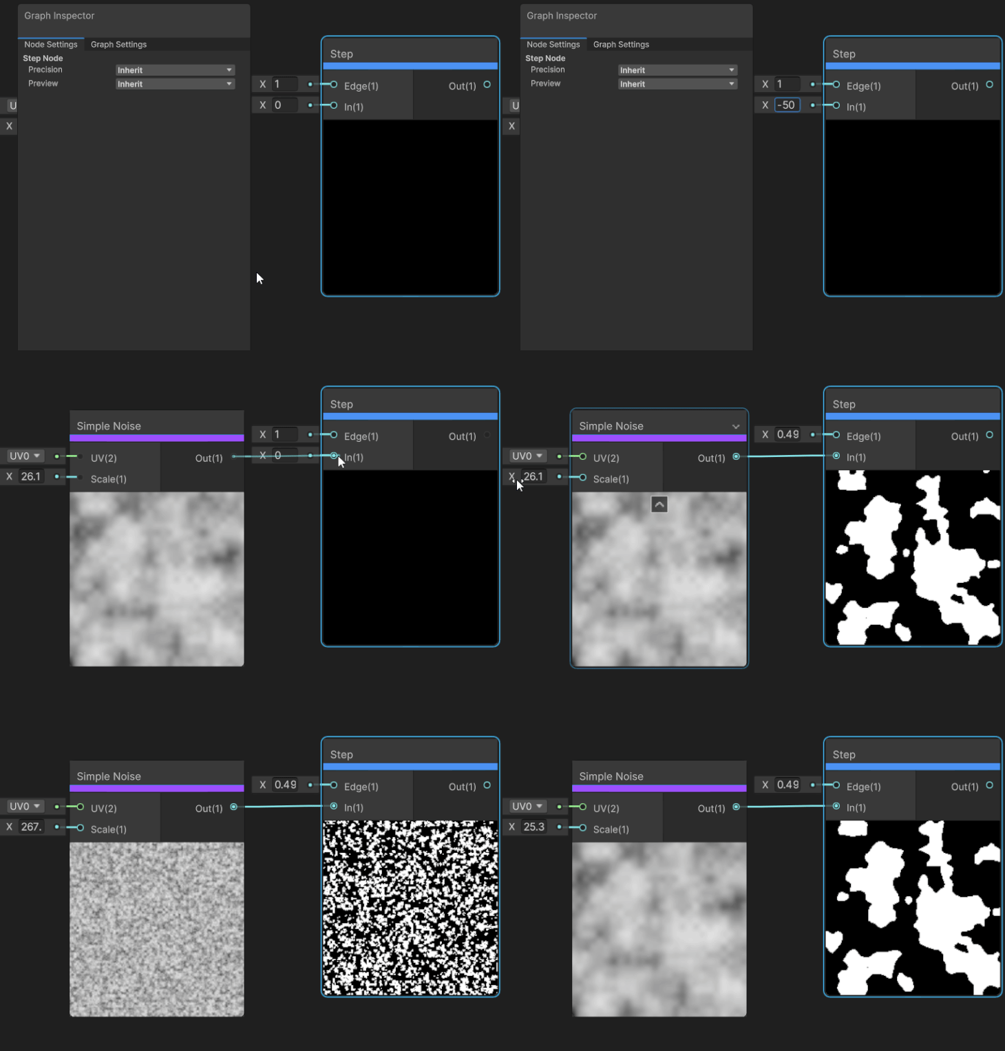
Step returns a 1 (true, white) or 0 (false, black) if the value input is above or equal to the value of input Edge.
Step Node inputs:
Step Node outputs:
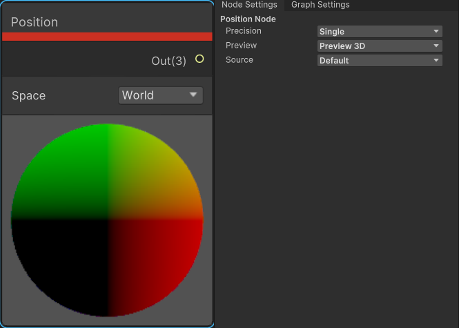
The Position Node provides access to the position of the vertex of the mesh; the position is relative to the selected space.
As an example, here’s what happens when the Position Node is connected to the Simple Noise Node’s UV input in the Dissolve Shader.
This is the result if Space = World:
And this is the result if Space = View:
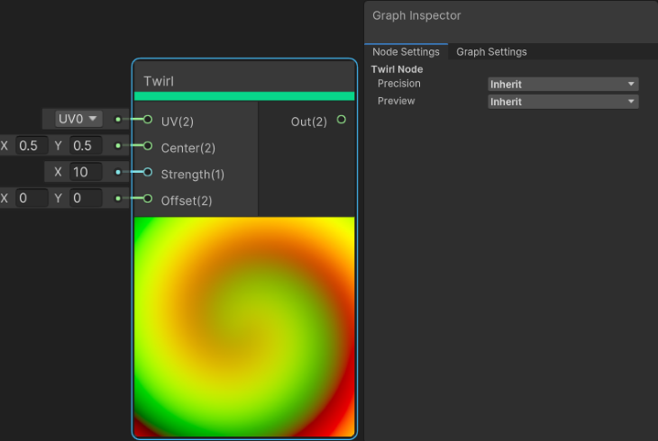
The Twirl Node applies a black hole–like warping effect to the value of input UV.
Node Settings > Preview: Inherit, Preview 2D, Preview 3D — the type for the Preview area
Inputs:
Outputs:
Preview: Visual Representation of what is outputted.
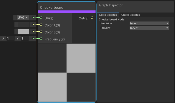
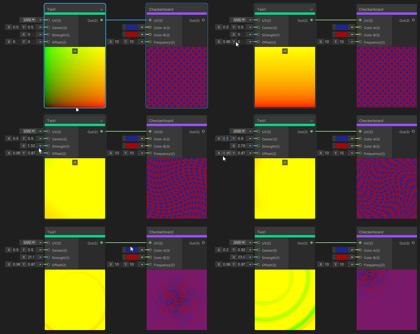
This generates a checkerboard with the colors provided; the scale is defined by the Frequency. This node is used to apply a checkerboard texture to a mesh, also useful for a visual in Shader Graph on what the effect of changing the UV by some value looks like.
Inputs:
Outputs:
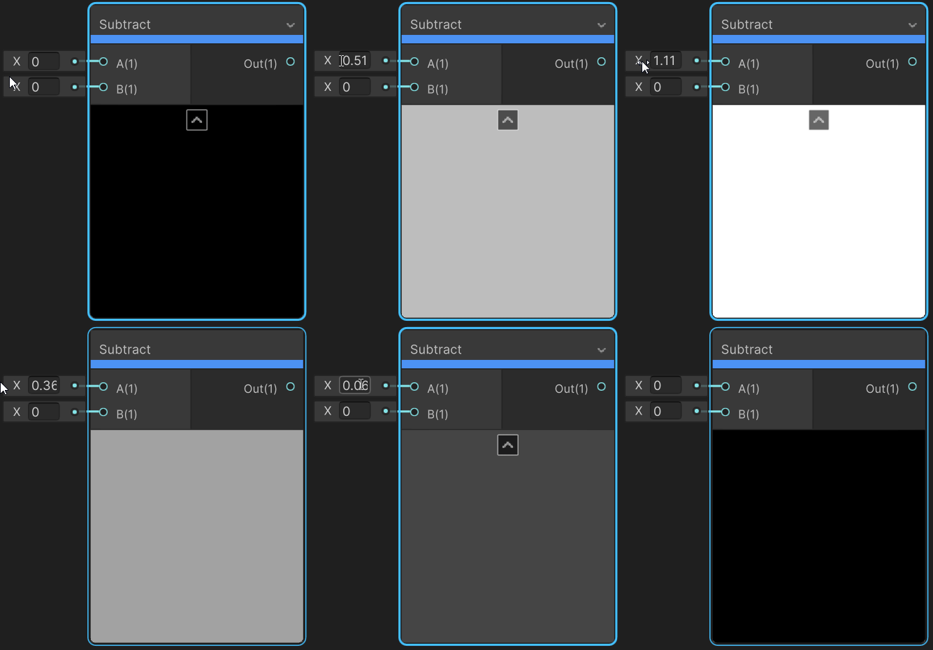
This node subtracts Input B from Input A
Inputs:
Outputs:
Preview:
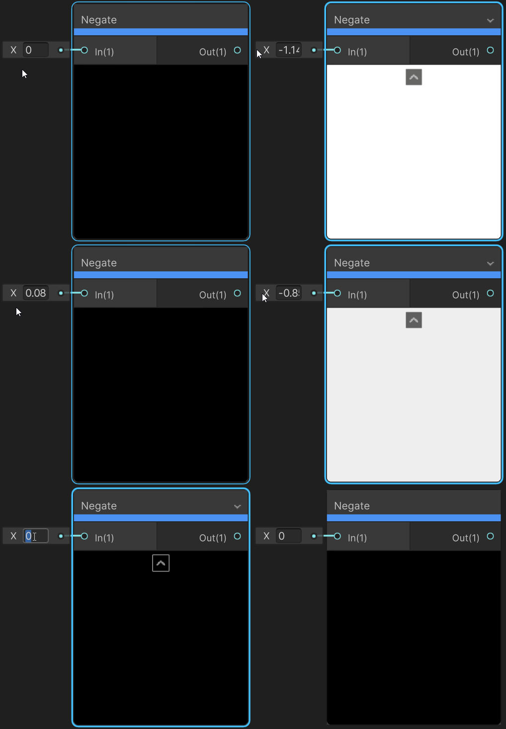
Negate flips the sign value of In. Positive values are now negative and negative values are now positive.
Inputs:
Outputs:
Preview:
With the addition of one more node, we can have the dissolve effect emit light.
To help keep things neat and easy to read, I made the dissolve effect a Sub Graph. I outputted the Step Node (this is what we had attached to the Alpha Threshold) and the Emission (we will need this for the Emission Block).
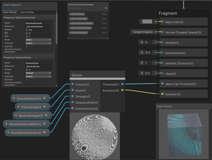
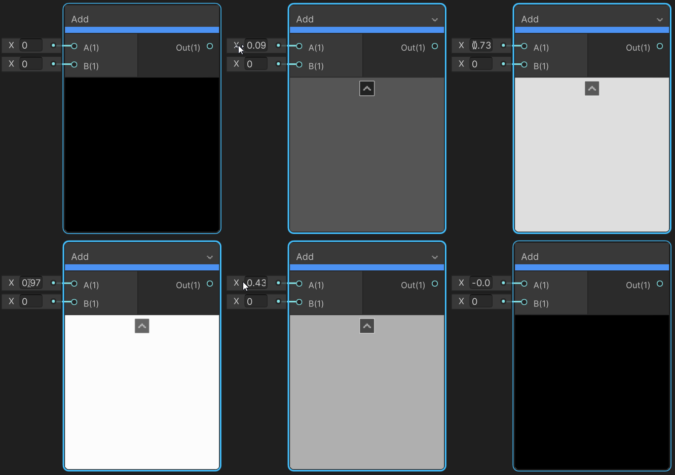
Add the two inputs together.
Inputs:
Outputs:
Preview:
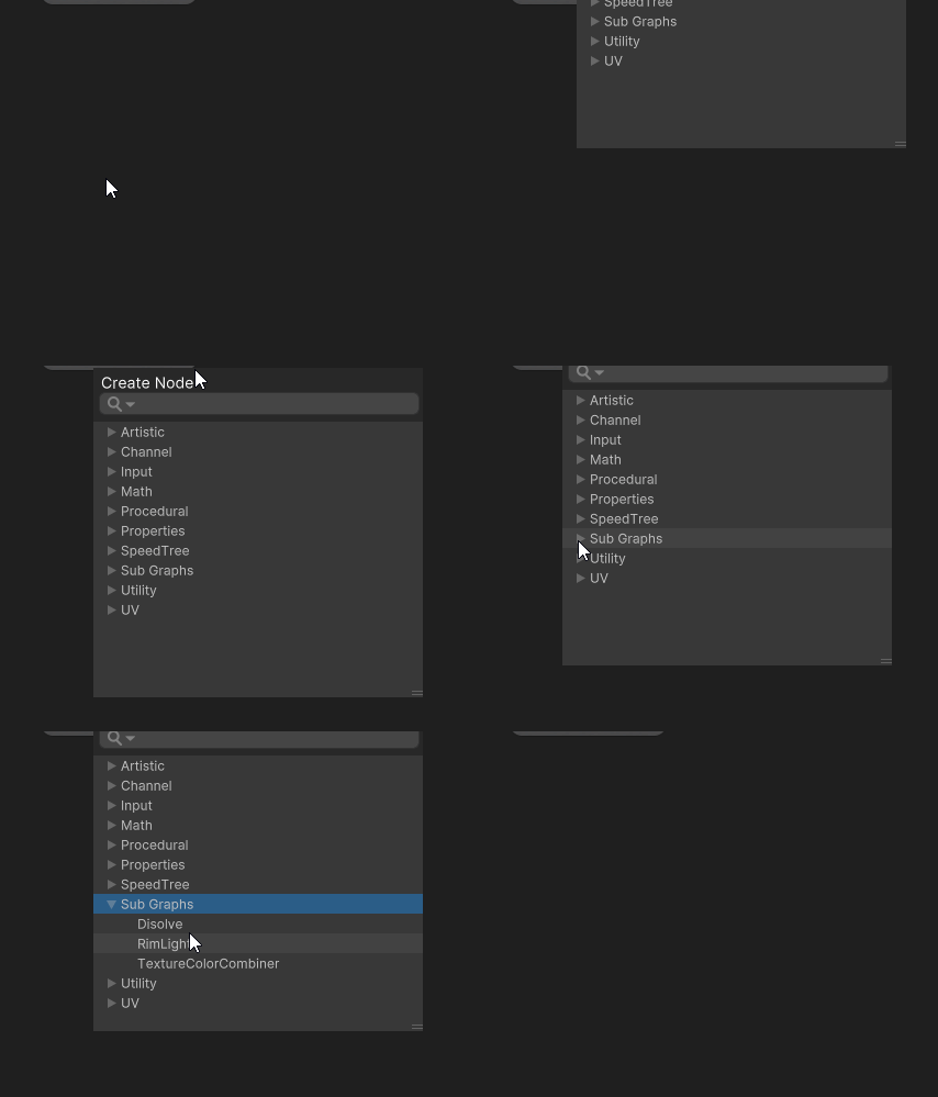
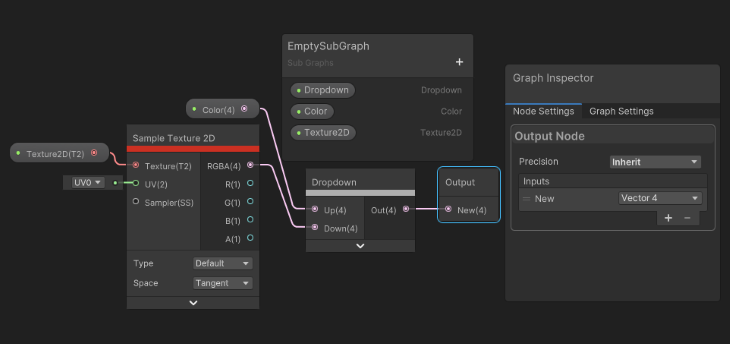
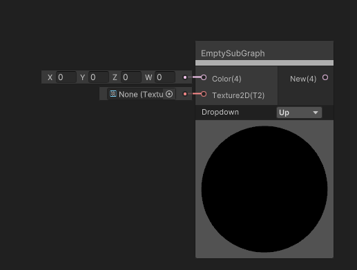
This allows you to add any of your custom created Sub Graphs.
You can include any dropdown properties defined on the Blackboard. For more info, see Subgraph Dropdown in the docs.
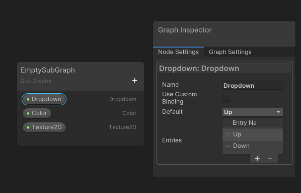
Inputs:
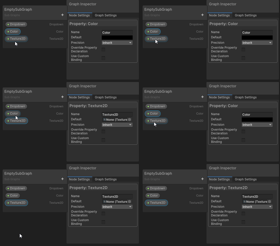
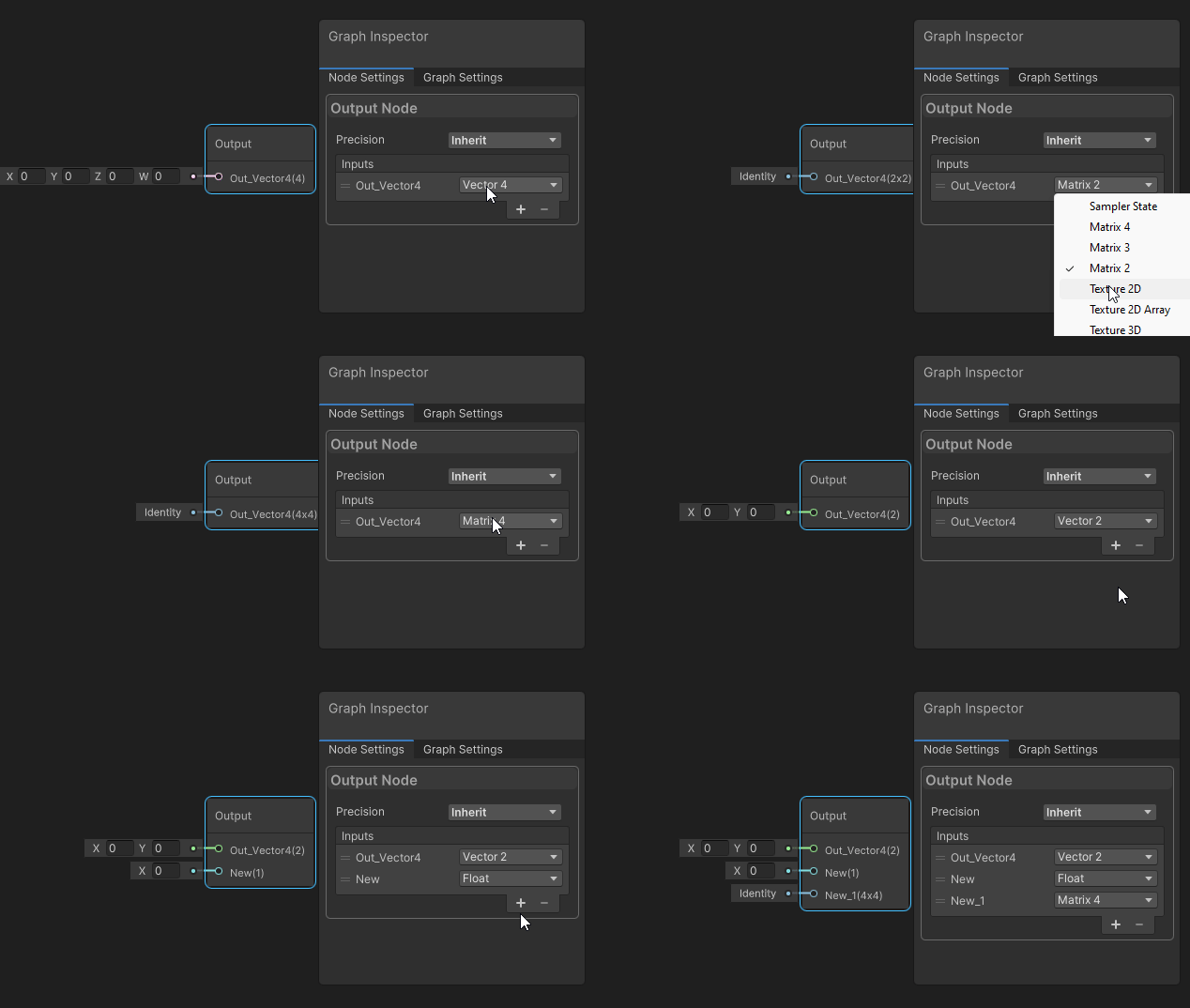
Outputs:
Now it is time to combine all of these into one Shader Graph.
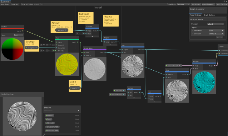
Here are each of the previous effects as a Sub Graph:
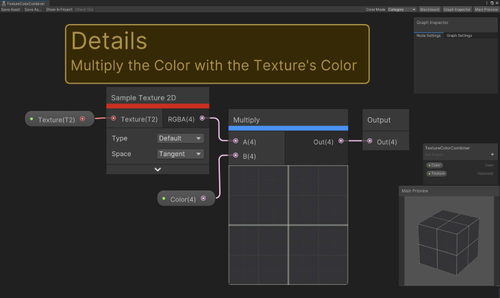
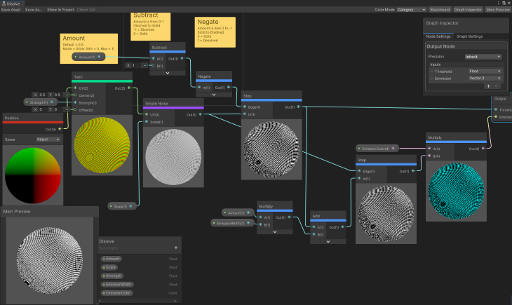
And the Shader Graph, using all of them together:
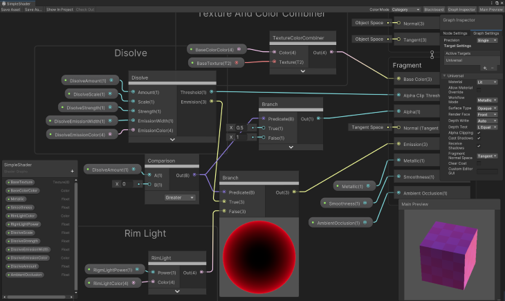
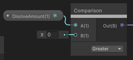
This node compares two values to a condition. It’s one of the many logic test nodes available; others are ALL, And, Any, Is Front Face, Is Infinite, Is NaN Nand, Not, and Or.
Inputs:
Outputs:
Out: Boolean result of comparison
The Preview is a visual representation of what is outputted.
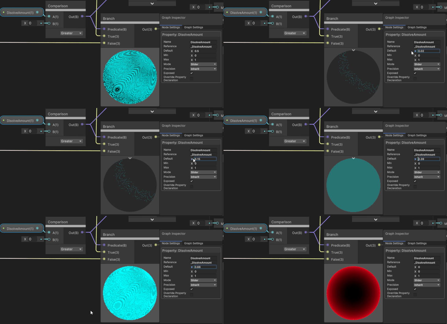
The Branch Node returns a value based on a true/false condition. The other Branching Node is BranchOnInputConnection.
Inputs:
Outputs:
The Preview is a visual representation of what is outputted.
There are some things to take note of in versions of Shader Graph that are older than version 10.0.x, whether you are upgrading from an older version or come across how someone created a shader and want to replicate it.
The big difference is the use of Master Stack instead of Master Nodes. What Blocks are available in the Master Stack depends on your Graph Settings. The use of multiple Master Nodes needs special attention. If you are upgrading, see Unity’s upgrade guide.
The other big difference between the two: all of the settings are now found in the Graph Inspector. The Graph Settings tab contains all of the graph-wide settings and the Node Settings tab contains all of the property settings and per-node settings.
There are some minor changes in the Graph Settings, like Two Side is not a checkbox, and you use the Render Face enum (Front, Back, and Both).
One last difference is the input for the Color Block of a Fragment Stack. This tip actually comes from Code Monkey’s video.
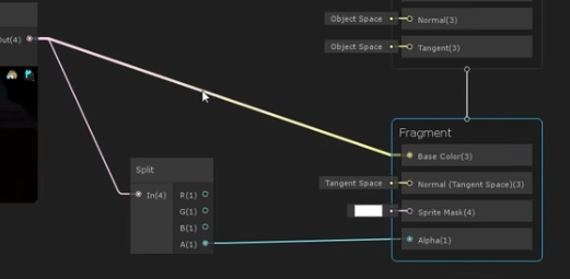
The Fragment Stack will contain a Color Block that takes a Vector4 value, which is RPGA. A newly created Shader Graph will have a Color Block that takes a Vector3 value, which is just the RPG color, and it has a separate block for the alpha.
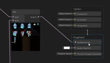
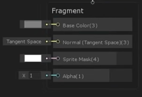
To get the alpha, you just add a Split Node and take the alpha output to the Alpha Block input. He pointed out that specifically for sprites, typically when dealing with shaders, if you are using the alpha of a color, you are specific about what the alpha value represents. Whereas with sprites, the expectation is that the alpha of the color controls the transparency.
Unity has several more resources if you’d like to keep learning:
Install LogRocket via npm or script tag. LogRocket.init() must be called client-side, not
server-side
$ npm i --save logrocket

// Code:

import LogRocket from 'logrocket';
LogRocket.init('app/id');
// Add to your HTML:

<script src="https://cdn.lr-ingest.com/LogRocket.min.js"></script>
<script>window.LogRocket && window.LogRocket.init('app/id');</script>

Claude Code is deceptively capable. Point it at a codebase, describe what you need, and it’ll autonomously navigate files, write […]

Compare the top AI development tools and models of February 2026. View updated rankings, feature breakdowns, and find the best fit for you.

Broken npm packages often fail due to small packaging mistakes. This guide shows how to use Publint to validate exports, entry points, and module formats before publishing.

Discover what’s new in The Replay, LogRocket’s newsletter for dev and engineering leaders, in the February 11th issue.
Hey there, want to help make our blog better?
Join LogRocket’s Content Advisory Board. You’ll help inform the type of content we create and get access to exclusive meetups, social accreditation, and swag.
Sign up now